
Introduction
This chapter provides the explanations on starting with the 5X Expert module:
-
What is the workflow in GO2cam; the selection and programming process and the general rules to follow.
-
The General 5 axes cycle; this mode contains all the required toolset to be able to machine any 5X part.
-
An overview of the other more specific cycles
Various tips on the usage of this module can also be found in the FAQ section. Click on the link to go to the page.
|
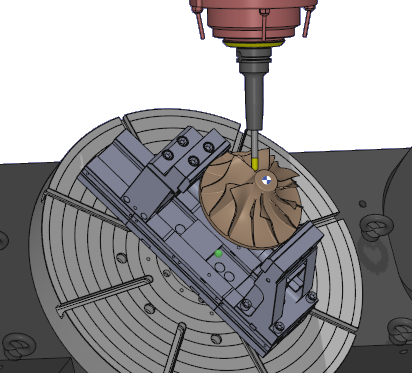
The 5X Expert menu provides additional and more powerful tools to tackle the machining of very complex parts. One common example of such a part is the impeller shown in the image. However, these tools are not proprietary to GO2cam, so the workflow slightly differs. GO2cam’s calculation is based on the solid model. Hence even when a face is selected to apply machining on, the software recognizes that face in association with the solid part. The 5X Expert module operates as a surface-based calculation engine. When a face is selected, only that surface is recognized, while associated solid surfaces remain undefined until specified in the process. |
|
The Workflow in 5X Expert
This introduces some variations in the general workflow of GO2cam and there are some specific rules that need to be followed:
|
1/ Always program the toolpath in the REFERENCE plane. The orientation of the tool is defined in the 5 axis strategy dialogs. |
||
|
2/ The programming steps are similar to the standard cycles with 3 steps but the order has to be followed. |
||
|
|
Selection of the faces to machine. The selection does not end at this point: most of the toolpath patterns need pilot curves or surfaces, that have to be selected inside the tab ‘Surface Paths’ of the machining cycle. |
|
|
|
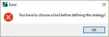
The choice of tool (or tool family) must be done before the selection of a machining cycle. |
|
|
|
Choice of the machining operation. This is followed by defining the various strategy parameters to control the toolpaths such as the surface paths, tool axis control, etc. |
|
|
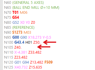
GO2cam Rapid Plane (defined in Movement page) is always taken into account for first entry and last exit, even if safety strategies have been defined inside the 5X cycles!
For instance, you may have a Z decomposed rapid movement (Z50 then Z40). But from version 2026.7, if the GO2cam Safety Plane value is lower than 5X Safety Plane, it is automatically deleted. |
|
|
|
|
3/ Calculation of the cycle. Due to the complexity and computation power required to calculate such toolpaths, it is recommended to carry out the strategy changes in an iterative manner. For instance, first apply and calculate the settings for the Surface path to confirm the toolpath shape, then move on to change the settings to control the tool angle and calculate, etc. |
|
Miscellaneous
Persistency of solid faces
|
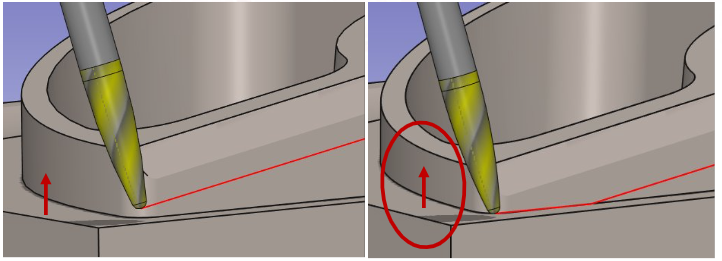
The toolpath calculation now incorporates real-time updates for all faces and surfaces. Modifications to solids or faces used for gouge checking automatically trigger toolpath recalculations. The example below demonstrates how a higher bottom face on the right side results in an adjusted toolpath. The 'Curve tolerance' option now controls Parasolid surface meshing. |
|
5X Cycles in opelist
|
|
Create and standardize complex machining strategies by developing 5-axis expert opelists. Define and insert all 5X cycles in opelists, which are now read and applied like other cycles.
▶️ Watch how to create 5-axis expert Opelist in GO2cam 2026. |
|
.