
General Information
|
Geometry These cycles are not calculated on 2D geometry but only on solids or surfaces (STL). The solid on the screen is automatically selected; to machine specific areas, you must define Limitations areas, on some cycles. Each cycle has his own behavior. |
|
|
Automatic Calculation The 3X cycles are more automated than 2X milling. Entry points, lead-in and lead-out types, and collisions differ from 2X milling. Users cannot adjust toolpaths or rapid motions as they usually do. The 3D shape and collisions are managed automatically. |
|
|
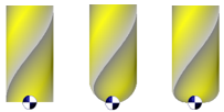
Typologies of Parts You can machine any type of solids:
|
|
|
Advises for Time Calculation Time calculation can be much longer than in 2X milling. Here are 2 advises: |
|
|
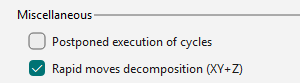
To postpone toolpath calculation, select Postpone execution of cycles in Tools > Options > Machining. This option creates all operations quickly; 3X cycles remain uncalculated and appear as “Waiting mode” in the Machining Tree. After programming, click Update to calculate all prepared cycles simultaneously. You may continue other tasks or run the calculation overnight. |
|
|
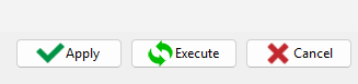
Another way to save time is to edit and modify the toolpaths in the strategy pages. Clicking Apply instead of Execute postpones calculation. You can make multiple modifications across cycles and calculate all at once. |
|
|
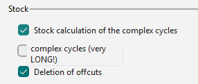
The choice of stock computation (Deactivate, Solid Stock, or Rapid Stock) affects computation time. By default, stock is not computed for 3X operations. You can change this setting in Tools > Options > Milling by selecting the Stock calculation option for complex cycles. Click the link for more details. |
|
Simulation
Simulate 3D parts can be long:
|
1 |
We implemented a special simulation type called Faster 3D (simulation option mode) |
|
|
2 |
As explained above, you can use the Comparison to verify actual stock removal. |
|
|
3 |
You can save the stock after the roughing operation as a X_T step (Machining Tree, Stock > Utilities > Export…) or as an STL file (Machining Tree, Stock > Simulation > Create STL file…). 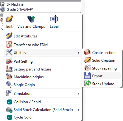
|
Then replace the stock with this file via Machining Tree, Stock > Simulation > Import STL/X_T for simulation. This file will simulate subsequent operations, significantly speeding up the simulation. 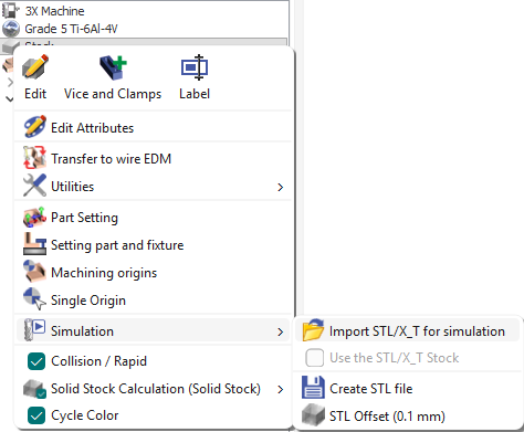
|
Tools
|
Piloting Tools: We generate toolpath on the tip of tool. ISO codes are also based on tip of tool, there is no need to define Tool correction. |
|
For specific post-processors, the behaviour can be changed to choose to calculate the toolpath on center tool position. |
|
Avoidance of Collisions
|

|