
|
|
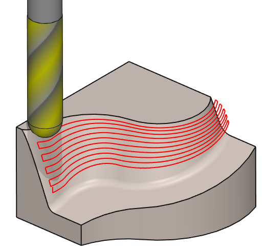
The Contour Morphing cycle is based on the same principle as the Pocket Morphing cycle.
|
Key Points
|
|
Strategy Parameters
|
Dialog Area |
Parameters |
|
|
Toolpath Strategy |
Zig Zag path |
|
|
Stepover Calculation |
Stepover (Tool ratio) |
Stepover value (Ae) |
|
XY Scallop |
|
|
|
Allowances |
XY Stock allowance |
Z Stock allowance |
|
Normal stock allowance |
|
|
Movement Parameters
|
Dialog Area |
Parameters |
|
|
Safety (in Z) |
Rapid plane alt. |
Safety distance |
|
Approach and return in Z |
Retract altitude |
|
|
Safety (in XY) |
SD/ Tool shank |
Management of toolholder |
|
Leadin and leadout in XY |
||
Technology Parameters
|
Dialog Area |
Parameters |
|
|
Cutting Conditions |
Quality |
Cutting Speed |
|
Feedrate/tooth |
Spindle direction |
|
|
Spindle speed |
Feedrate |
|
|
Sp. speed range |
||
|
Tool number |
Specific Number |
|
|
Length compensation number |
Diameter compens. Nb |
|
|
Users Fields |
Comment |
Control Device |
|
Milling Set |
|
|
Options Parameters
|
Dialog Area |
Parameters |
|
|
Behaviour on the clamps and components |
Gouge Check |
Offset XY |
|
Offset Z |
||
|
Curves Computing |
Curve tolerance |
Curve segmentation |