
|
|
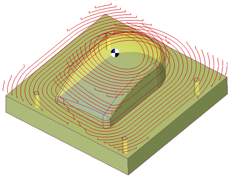
The Stock rework roughing allows to resume the part with a stock management. GO2cam searches for the material remaining at the time of the application of the roughing cycle by comparing the polyhedron covering the solid or the surfaces, and the polyhedron resulting from the preceding machining phases. |
Key Points
|
|
Strategy Parameters
|
Dialog Area |
Parameters |
|
|
Toolpath Strategy |
Machining Direction |
|
|
Optimization |
|
|
|
Limitation of Machining |
||
|
|
||
|
Undercut and Reworking |
Undercut machining |
Island reworking |
|
Scallop reworking |
Scallop value |
|
|
Stock Computing |
||
|
|
||
|
Stepover Calculation |
Stepover (Tool ratio) |
Stepover value (Ae) |
|
XY Scallop |
Respect of scallop |
|
|
Z Step |
Z Step (Ap) |
|
|
Allowances |
XY Stock allowance |
Z Stock allowance |
|
Normal stock allowance |
|
|
|
List of altitudes |
List of altitudes |
|
Movement Parameters
|
Dialog Area |
Parameters |
|
|
Safety (in Z) |
Rapid plane altitude |
Safety distance |
|
Approach and return in Z |
Approach altitude |
Retract altitude |
|
Return altitude |
|
|
|
Z Plunge |
Plunge |
Mini helix rad. |
|
Mini ramping rad. |
Mini rad mach area |
|
|
Plunge angle |
|
|
|
Management of rapids |
Motions: Rapid, G1 Fmax, G0/G1 Fmax |
Fmax safety distance |
|
Rapid/Fmax % |
|
|
|
Safety (in XY) |
XY safety distance |
SD/ Tool shank |
|
Management of toolholder |
|
|
Technology Parameters
|
Dialog Area |
Parameters |
|
|
Cutting Conditions |
Quality |
Cutting Speed |
|
Feedrate/tooth |
Spindle direction |
|
|
Spindle speed |
||
|
Feedrate |
Sp. speed range |
|
|
Tool number |
Specific Number |
|
|
Length compensation number |
Diameter compens. Nb |
|
|
Users Fields |
Comment |
Control Device |
|
Milling Set |
|
|
Options Parameters
|
Dialog Area |
Parameters |
|
|
Behaviour on the clamps and components |
Gouge Check |
Offset XY |
|
Offset Z |
||
|
Toolpath Optimization |
Treat maxi stepover |
|
|
Feedrate reduction coef |
Maxi stepover coef |
|
|
Type of HSM radius |
Radius of HSM loop |
|
|
Radii on contour |
|
|
|
Curves Computing |
Curve tolerance |
Curve segmentation |
|
Toolpath Computing |
Decomposition of arcs of toolpath |
Arcs decomposition tolerance |
|
Cooling |
||