
|
|
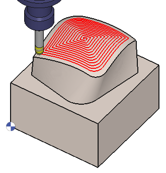
The Pocket Morphing cycle is a pocket cycle with evolving trajectories depending on the selected reference profile and the solid. The trajectories will gradually adapt from the selected profile to the shape of the part. |
Key Points
|
A reference profile corresponding to the pocket must be defined. So that the trajectories are generated inside and from it, evolving relative to the surfaces of the pocket. Machining will be from the center to the profile or vice versa. |
|
Strategy Parameters
|
Dialog Area |
Parameters |
|
|
Toolpath Strategy |
Machining direction |
Machining Method |
|
Path direction |
|
|
|
Definition of Machining Area |
Machining Area/Reference |
Offset type |
|
Offset on drive profile |
|
|
|
Stepover Calculation |
Stepover (Tool ratio) |
Stepover value (Ae) |
|
XY Scallop |
|
|
|
Allowances |
XY Stock allowance |
Z Stock allowance |
|
Normal stock allowance |
|
|
Movement Parameters
|
Dialog Area |
Parameters |
|
|
Safety (in Z) |
Rapid plane alt. |
Safety distance |
|
Approach and return in Z |
Retract altitude |
|
|
Safety (in XY) |
SD/ Tool shank |
Management of toolholder |
|
Leadin and leadout in XY |
||
Technology Parameters
|
Dialog Area |
Parameters |
|
|
Cutting Conditions |
Quality |
Cutting Speed |
|
Feedrate/tooth |
Spindle direction |
|
|
Spindle speed |
Feedrate |
|
|
Sp. speed range |
||
|
Tool number |
Specific Number |
|
|
Length compensation number |
Diameter compens. Nb |
|
|
Users Fields |
Comment |
Control Device |
|
Milling Set |
|
|
Options Parameters
|
Dialog Area |
Parameters |
|
|
Behaviour on the clamps and components |
Gouge Check |
Offset XY |
|
Offset Z |
||
|
Curves Computing |
Curve tolerance |
Curve segmentation |