
|
How to apply margins in 5X Expert machining cycles?
|
|
|
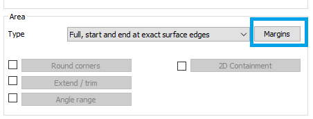
The margins parameter is available in the case where you have set the area type to 'Full, start and end at exact edges' or 'Determined by number of cuts' for the General 5 axes cycle.
|
|
|
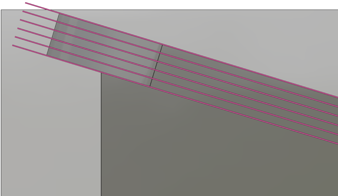
Cuts begin or finish right at the edges of your drive faces. The toolpath along the surface edge is set in a defined position. This positioning allows you to define a margin value to determine the space between the edge and where the cutting starts and ends.
|
|
|
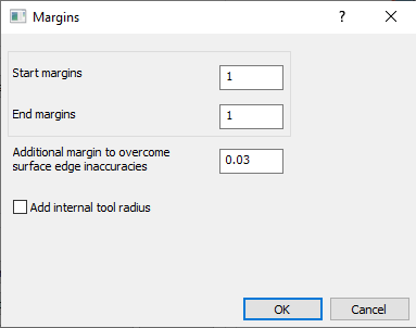
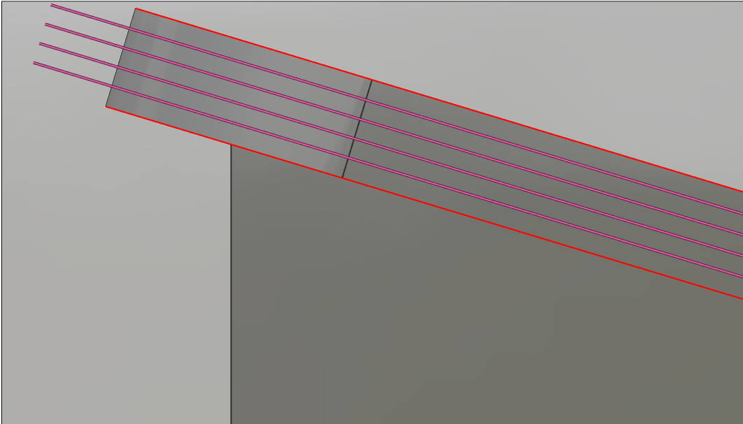
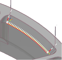
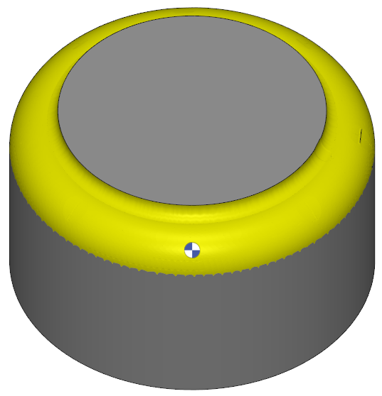
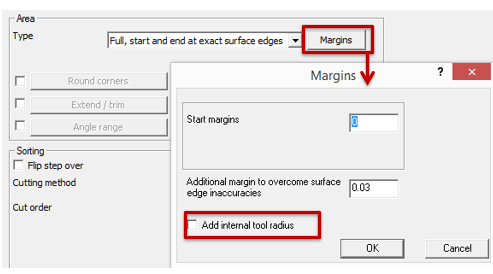
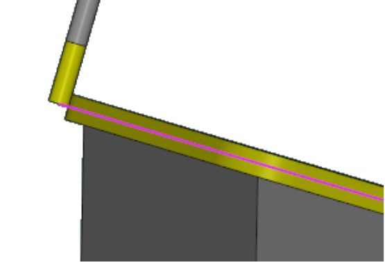
An example is the below part. The pattern set is 'Morph between two curve'. If no margin is set, the tool centre will path through the surface edge and gouge with the surfaces outside the drive face and risking collision. When you set a margin of the tool radius, the tool will be offset from the edge and it won't gouge. It is recommended to at least set the tool radius as margin. The start margin belongs to the first curve and the end margin to the second curve. An 'Additional margin to overcome surface edge inaccuracies' can also be defined to ensure there is no gouge. In this case, a start and end margin of 1mm is set and additional margin of 0,03mm included |
|
|
|
|
You can watch a video with the example on the right. |

|
|
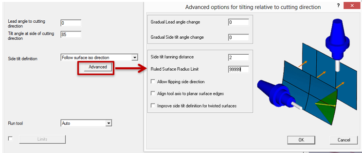
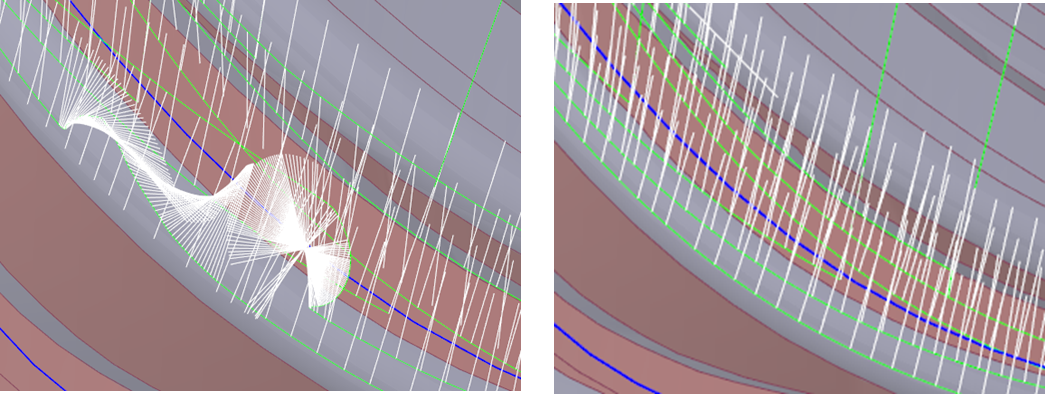
How to force tool to tilt in a only one direction?
|
|
|
When the tool rotates unexpectedly, it is unable to identify the surface's UV curves.
|
|
|
|
|
|
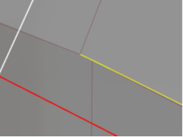
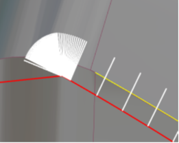
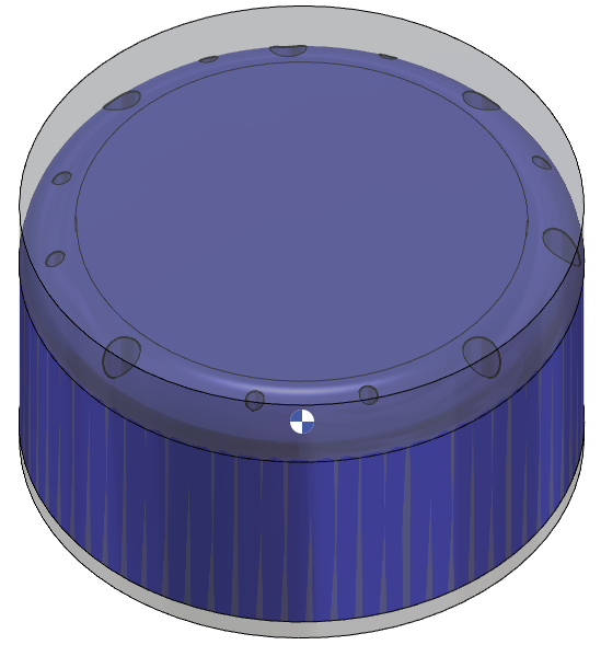
How to avoid unwanted tool vector orientation when pattern with curves are chosen ?
|
||
|
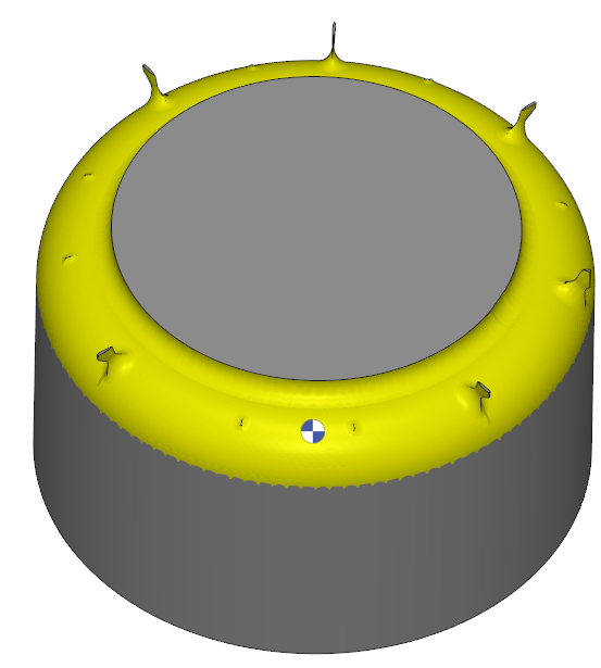
In certain cases, selection of curves through edges may be easier. However, broken edges where the link of the interconnecting surfaces become difficult to compute, the tool motion at that point generated unwanted vectors. |
|
|
|
In such cases, to correct this issue it is recommended to use the face option for the curve selection. This eliminates the risk posed by broken edges and the machining toolpath and the tool vectors are generated appropriately. |
|
|
|
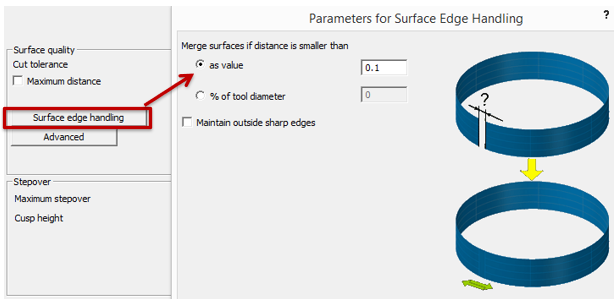
What is Surface edge handling?
|
||
|
Surface edge handling, helps to prevent common issues such as gaps, overlaps, and unexpected behavior, ensuring a smooth and accurate machining process. Merging surfaces is an effective way to address edge accuracy issues. You can set the merge distance as a fixed value or a percentage of the tool diameter." By effectively managing surface edge handling, you can:
|
|
|
|
|
|
|
What happen when internal tool radius is activated? |
|
|
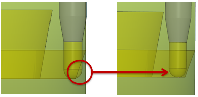
To maintain adequate clearance in pencil trace machining, the internal tool radius must be factored into the margin for the leading curve or surface. Activating this option will add the tool radius to the specified margin, ensuring the toolpath remains tangent to the side surface with a radial offset. |
|
|
|
|
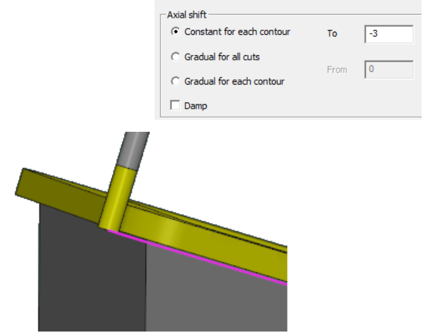
What is axial Shift? |
|
|
Axial Shift is an offset applied to the tool along its axis. It can be used control the depth of cut and the tool’s contact point with the workpiece. The different methods for axial shift:
|
|
|
|