
|
How can I have 2 different tools in a synchronized cycle?
|
||
|
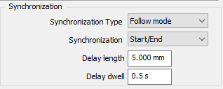
Define your Balanced Roughing/ Balanced Finishing cycle as usual with the required synchronization settings. In this case, since a single tool has been chosen, the same tool will be loaded twice in MTE. 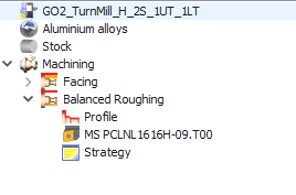
|
|
|
|
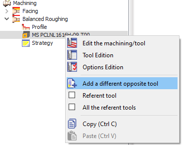
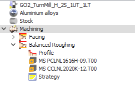
To be able to set a different second tool, expand the cycle in the machining tree. Right-click on the existing tool select 'Add a different opposite tool'. This will open the tool selection window again where you can choose the tool you require and validate. Both tools will be visible in the machining tree now. In MTE, if you do Auto mount, these 2 tools will automatically be mounted on opposite turrets. |
|
|
|
You can watch a video explaining the application of the balanced synchronized cycles. Skip to 2.20 in the video to view the definition of 2 different tools for the cycle. |

|
|
|
How to duplicate tool in MTE?
|
|
|
In turning to duplicate tool,
|

|
|
How does WanaGO determine if a machine can accept a part?
|
|
WanaGO determines if a machine can accept a part based on the following criteria:
In essence, WanaGO ensures that the machine is both physically large enough to accommodate the part and strong enough to handle its weight. |
|
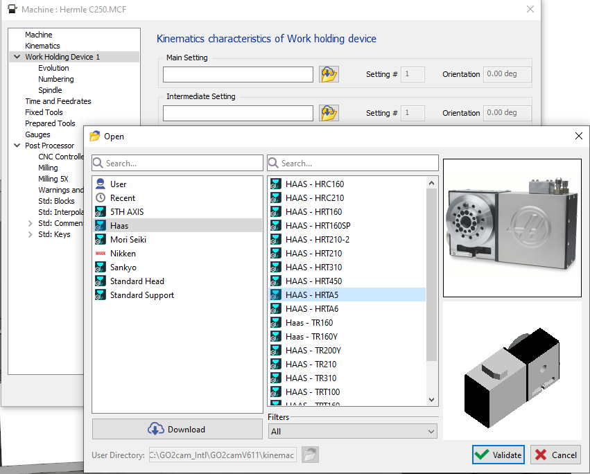
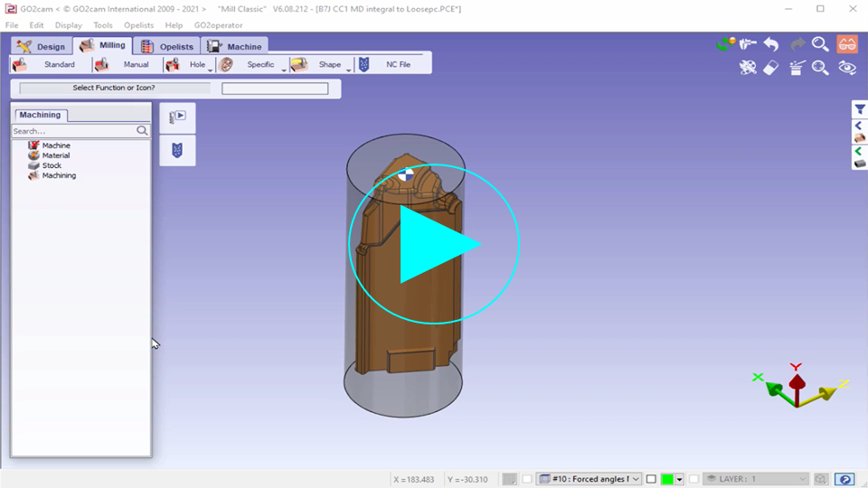
How to program a part on a rotary table?
|
|
|
|
|
|
▶️ This video demonstrate a 4 axis programming of roughing and how to setup a rotary table. |
|

|
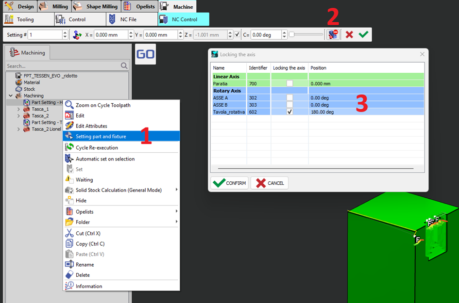
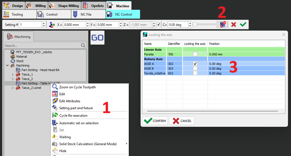
With a milling machine with 6 axes (3 angular axes), is there a mode to lock one angular axis and move the other two?
|
|
|
Yes, this is possible using appropriate part settings in your GO2CAM. For example, consider a 6-axis milling machine with:
If you need to lock the C axis at a specific position (e.g., C180) and allow movement on B and A, you can achieve this by setting up a part setting in the CAM environment (e.g., GO2cam). Here's how:
|
|
|
My tool machines the opposite side of the profile selection because it is positioned on the lower rack of the machine. How can I properly program this tool?
|
|
|
3 solutions are possible:
|

|
|
How can I park the turret in 2 or more positions?
|
|
|
In MTE extra settings for the machine, only a single position can be set for the Parking function. The solution to have multiple parking positions is to use the Move a component function. It is recommended to define the function as an opelist to facilitate reuse. See the video on the right. |

|
|
How can I properly index my tool on a turret with multiple indexing position per station?
|
|
|
From Version 6.12.204 we can manage this situation! An example is used for a turret with 12 stations and 24 indexing positions! To index a tool on the turret define the indexing angle in the toolholder. In the clamping/ toolholder creation module, open the required toolholder and in the mounting options, insert the angle which is 15 deg (360/24) for this setup and save. When using the indexing the turret command, it can be seen that both tools on the toolholder are indexed properly. |

|
|
Why do I still have red warnings for unreachable angles in the machine planes dialog even though I have properly oriented my tool angle to reach the machining face?
|
|
|
Cause of the problem: This is usually an issue with the precision set for measurements in the Software configurations. Measured values are rounded off to the precision set while the actual angle is at a higher degree of precision, thus causing the problem. As from GO2cam 2026, obtaining the B and C angle for an inclined hole is easy with a simple measure. The value is also provided in the Information dialog and can be copied. Solution for the issue: Set the precision to higher degrees in Software configuration to obtain the true angle value. The Delta angle value is provided in the Information dialog when opening the Machining Planes dialog. Copy the value and add it to the oriented angle of the required tool. Recommended practice: There is no need to adjust the measurement precision in Software configurations. Set the tool rotation angle to 0 and open the Machining planes dialog. The delta angle to set the tool is provided in the information dialog warning, at the required precision. Copy and paste the value for the tool rotation. |

|
|
Why do I have a different number of mounted tools than the number of tools I have used for programming when I do automounting?
|
|
|
Cause of the problem: Often, the same tool is defined for multiple operations but requires distinct mounting positions in the machine for each. GO2cam usually automatically detects when a tool is needed multiple times and duplicates it during automounting. In some cases, the automatic detection may fail and the tool is not duplicated, instead the same tool is given multiple tool position numbers. If a tool cannot reach the angle/direction it needs to machine, the line in the List of Tools window will be displayed in red, preventing the MTE simulation from running. |
|
|
Solution 1 for the issue: When launching the automounting process, tick the “Reset of tool numbers” checkbox. This refreshes the detection algorithm and ensures the tool list is accurate. 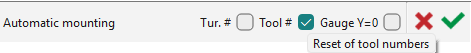
This method resets all tool numbers, including any manually set. |
|
|
Solution 2 for the issue: Perform automounting as usual without resetting. The List of Tools dialog displays the same position choice three times, for example, for the 10mm drill. For similar tools, a combo box provides a dropdown list of suitable position choices. 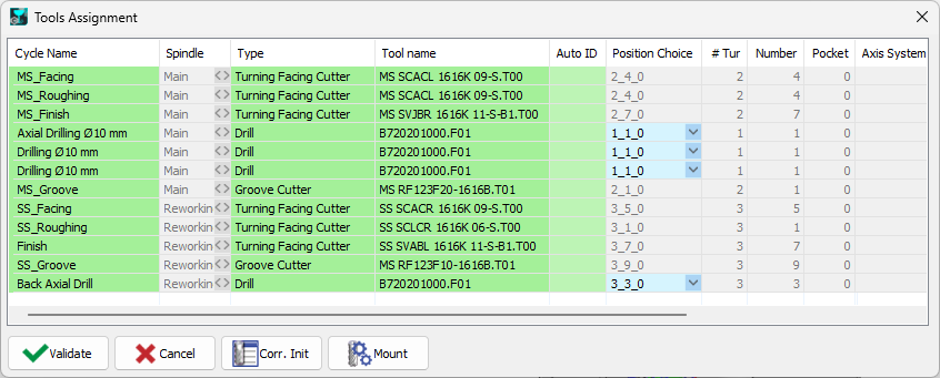
This allows to manually set the positions for each of them. |
Watch a video demonstrating such an operation. 
|