
|
|
Allows to program specific motions of components/axes of the machine manually. |
Description
|
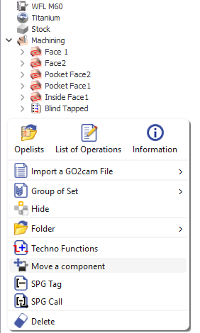
The function is available directly through a pop-up by right-clicking in the machining tree. A ribbon is activated as shown below: This function is also available via Techno Functions, accessible with a right-click. The ribbon is similar, but includes a list of techno functions—select Move Component in this case. Label/name the function by typing in the first field on the left. To define the actions of the function click on the icon encircled in blue on the ribbon (Creation of order for the simulation of machine components). This opens the Machine order dialog box that assists in defining the parameters for the motion. 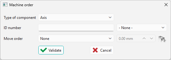
|
|
Dialog Box
Three parameters have to be set in the dialog box to define the Move component function. These are discussed below:
|
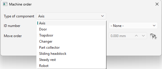
Type of Component A dropdown list is provided with the different components of the machine, including non programmable ones such as the door, that can be selected to program the motion. |
|
|
|
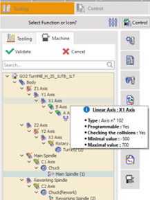
ID number The ID number is defined for each axis during the machine creation and definition phase which is handled by the reseller. The recommended labelling principle set by GO2cam is as such: Z axis ID = x01 X axis ID = x02 Y axis ID = x03 x is the Channel / Turret ID In MTE Tooling, under the machine sub-tab, the user can check the axis label by hovering over the axis. The label is given in the info bubble as the Type. |
|
|
|
|
A dropdown menu is available next to the ID number field, allowing the user to browse and select identified components . Selecting a component adds it instantly to the ID list, separated by commas when multiple IDs are added. This reduces the need to remember and apply the labelling principle. 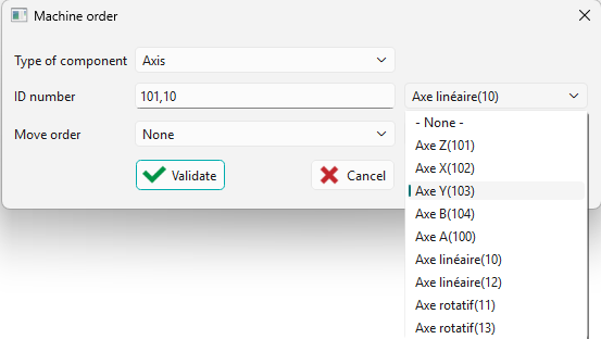
|
Watch the video below demonstrating the mechanism and component selection by ID in a machine.

|
|
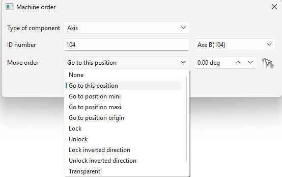
Move Order These are the actions that will be carried out by the defined component. The list of actions are given in the drop-down list and for some a value of the movement can be provided. |
|
|
|
|
The units are updated automatically based on the selection:
|
|
|
▶️ Watch a video on the right showing a quick example of the Move a component function. |

|
|
Using Move Component as an Opelist
|
Special Case: Parking the Turret In the case where we want to park the turret in the 2 extremities of the lathe machine to avoid damage risk from chips and collision risks, the move a component function is useful in defining these motions. An opelist is used to group the motion of the 3 axes ensuring repeatable use without having to tediously redefine the Move a component functions for all 3 axes again. ▶️ The video on the right demonstrates such an example. |

|