
|
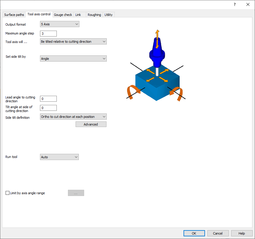
This tab provides the parameters and settings to control the tilting and control of the tool with respect to the part, about its axes to avoid collisions. The various parameters are briefly introduced below. |
|
|
Output format |
This parameter sets the output format for 3-, 4- or 5-axis machining. The output for 5-axis machining uses the complete freedom of the tilt range. This freedom is limited by 1 degree for 4-axis machining and 2 degrees for 3-axis. For 4-axis output, the portion of the 5th axis is projected back onto the selected 4th axis. For 3-axis output, the portion of the 5th and 4th axes is projected back onto the selected 3-axis machining direction. This parameter influences the behavior of the tool contact point. |
|
Maximum angle step |
This option sets the maximum allowed angle change between two consecutive toolpath positions. The calculation engine outputs 5-axis toolpath data that contains the tool tip position and the direction vector of the tool. The direction vectors are not allowed to have an angle change greater than the value specified here. 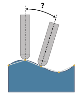
|
|
Tool axis will… |
Not be tilted and stays normal to surface |
|
Be tilted relative to cutting direction |
|
|
Tilted with the angle The tool axis will be tilted from the surface normal direction towards the tilt axis. The tilt axis can be the X, Y and Z axis or any line created in the geometry. |
|
|
Tilted with fixed angle to axis The tool axis will be tilted from the tilt axis towards the surface normal. The tilt axis can be the X, Y and Z axis. or any line created in the geometry. |
|
|
Rotated around axis |
|
|
Tilted through point The tool axis is always pointing from a created point in geometry to the surface point. |
|
|
Tilted through curve |
|
|
Tilted through lines The tool axis will be aligned to given tilt lines that have to be selected as geometry. |
|
|
Tilted from curve away |
|
|
Tilted from point away |
|
|
Be tilted rel. to impeller machining layer The tool will stay normal to the floor face of the impeller. The tilting to the lead and lag can be tweaked by a global lead/side angle and additionally with a local lead angle at the leading edge, splitter edge and trailing edge. |
|
|
Be tilted relative to contact point |
|
|
Tilted with fixed angle to surface normal |
|
|
Run tool |
This parameter defines the contact point of the tool and drive surfaces. Optional settings:
|
|
Limit by axis angle range |
|