Creation of a Hole Model by Formula with Constraints
A hole model can be made more flexible with the use of formulas especially in the list of operations. To be able to create these formulas based on the holes' characteristics, whatever the hole shape, number of stages, and options defined, automatic referencing is required.
Hole Characteristics Referencing
The referencing in GO2cam is automatic and follows the following rules:
a letter to define the parameter or the characteristic (in blue below)
a number relative to the stage (in red below)
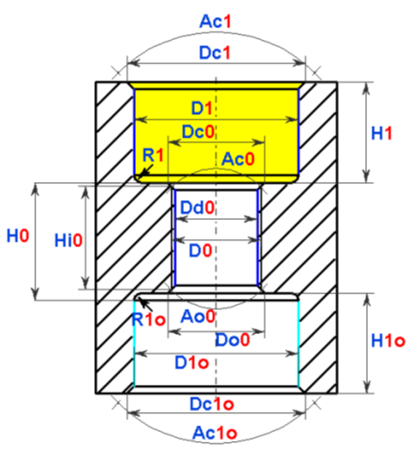
An illustration of a through hole with 3 stages is provided below to show the references:
H: height of the stage In the operation list, Height (H) is replaced by Machining Depth (P). D: diameter of the stage Dc: diameter of the stage chamfer Ac: aperture angle of the stage chamfer R: radius in the bottom of the stage For the tapped stage: D: tapping diameter Dd: drilling diameter Hi: tapping height Tp: tapping pitch Do: diameter of the inverse chamfer of the stage Ao: aperture angle of the inverse chamfer of the stage There are also 2 more parameters applicable only for the operation list: L0: total length of the hole z0: value added at the end of path to make the path longer and avoid |  The stages are numbered 1, 0, 1o |
Definition of Hole Parameters
During the process of creating the User Hole, each parameter can be calculated according to a mathematical formula using other parameters. Syntax to respect:
| |||||||
Mathematical operators | |||||||
sqr | Square | max | Maximum | acos | Arccosines | rnd | Random |
sqt | Square Root | min | Minimum | asin | Arcsines | log | Decimal Logarithm |
sin | Sinus | mod | Modulo | atan | Arctangent | sgn | Sign |
cos | Cosines | exp | Exponential | ^ | Power | round | Rounding |
tan | Tangent | Ln | Napierian Logarithm | abs | Absolute value | trunc | Truncation |
int | Integer value | ||||||
Binary operators: | Comparison operators: | Priority operators: | Logical operators: | ||||
+ | Addition | > | Superior to | ( and ) | OR | Logic Or | |
- | Subtraction | >= | Superior or equal to | Special Value: | AND | Logic And | |
/ | Division | < | Inferior to | Pi | XOR | Exclusive Or | |
* | Multiplication | <= | Inferior or equal to | NOT | Logic No | ||
= | Assignment | <> | Different from | ||||
== | Equality | ||||||
Errors: If the parameter uses its own reference in the calculation formula, a ‘Self-referenced variable’ error is shown. Similarly an error is shown if the value defined for a parameter is too small. For example, the chamfer diameter is defined as inferior to the nominal diameter: Dc1 = " [D1] – 1.5 " | |||||||
Formulas & Constraints in the Operation List
Parameters of the operations:
The parameters are divided in 3 categories:
Hole definition: execution of the cycle according to a constraint or not, unit and quality of the hole, definition of the machining depth. An interesting parameter is the weight, which enables to modify the positions of the operations. By default, all the cycles have a weight set to ‘0’, giving a weight of ‘1’ to an operation means positioning it at the last position (1 is heavier than 0). To position a cycle in the 1st position, define the weight to value ‘-1’.
Tool search: you can define a maximum value to the diameter.
Strategy: access to several strategy parameters of the cycle, such as the dwell and the Z offset. The incremental depth is interesting, you can base your calculation on a formula, for example in drilling deburring, you can define an increment equal to 1 tenth of the hole length. Please read above the chapter dedicated to formula creation.
Formula with conditions
Contrary to formula defined in the stages pages, these formula are not only calculation formula. Calculation formulas are possible, but here the great advantage is the ability to create constraints and then define an inter-dependence between several parameters.
Each dimensional parameter of the hole is defined with a reference, the complete list is given previously. The parameters described there are identical, except that we replace the stages heights (H) by machining depths (P)
2 parameters are added to this list:
L0: Total length of the hole. This value is given when applying a model on a part.
z0: over length value at the end of machining. You define this value in the hole options.
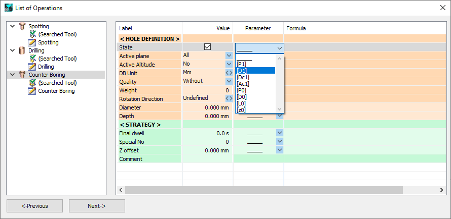
Thanks to the parameter ‘State’, we will be able to constraint the realization of a cycle by a formula. Here is an example: a counter bored hole with 2 stages. We want to define a spotting operation to be done only if the drilling diameter is bigger than 10 mm. For this, we first need to activate the check box in the line ‘State’ / column ‘Value’. Then choose the drilling diameter in the list of parameters, which is D1. |  |
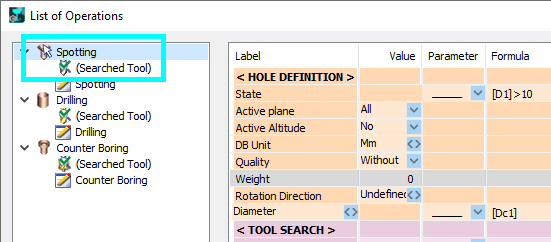
In the Formula field, enter [D1]>10. In the list of operations, you will notice that a small white pointer arrow is positioned on the spotting icon, to indicate that this cycle is constrained by a formula. |  |
When applying this model, simply fill the fields with the needed values and the operation list will be created taking the constraint into account. Here, 2 holes with different values:
|
Exercise
Here is an exercise to practice using the parametric formulas in the list of operations. We are going to create a hole model for the standard hexagon socket head cap screws M3, M4, M5, M6, M8, M10, M12, M16, M20 and more.
The hole is a through hole, counter bored, chamfered and tapped.
There will be 2 operations lists, one with conditions:
A. for counter boring which diameter is < to 18
B. for counter boring which diameter is > to 18.
Operations Lists | |
A. Diameter <= 18 | B. Diameter > 18 |
Chamfering Spotting | Spotting |
Drilling | |
Counter Boring | Pocketing |
Tapping | |
| Chamfering / Interpolation |
Here is the table of operations lists per counter boring diameter:
Screw | Counter Boring Diameter D1 | Chamfering Spotting | Spotting | Drilling Dd0 | Counter Boring | Pocketing | Tapping D0 | Chamfer by interpolation |
M3 | 8 | X |
| X | X |
| X |
|
M4 | 10 | X |
| X | X |
| X |
|
M5 | 11 | X |
| X | X |
| X |
|
M6 | 13 | X |
| X | X |
| X |
|
M8 | 18 | X |
| X | X |
| X |
|
M10 | 20 |
| X | X |
| X | X | X |
M12 | 22 |
| X | X |
| X | X | X |
M16 | 30 |
| X | X |
| X | X | X |
M20 | 36 |
| X | X |
| X | X | X |

