FAQ - Graphic User Interface - Configurations
Can I work in the same project with several different units in GO2cam? | ||
Yes, it is possible. We can list different situations where the user needs to work with several units:
This is why it is so important to have the unit displayed into the fields of geometric but also machining cycles dialogs. This is not only informative, you can type the unit in the fields to proceed to a conversion! | ||
For instance, here we create a line by entering 3.5 in, that is automatically converted to 88.90 mm. | 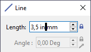 | 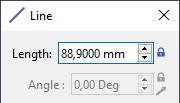 |
The circles and cylinders are faceted! | 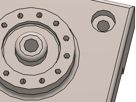 | |
You should modify the Tracing Precision. You can find it in the bottom right corner and also in Tools>Options>Entities | 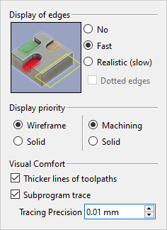 | 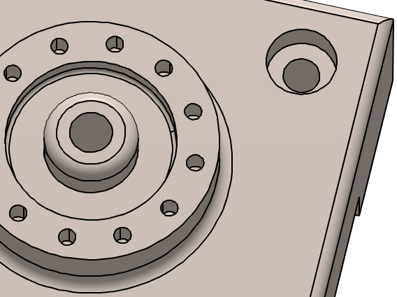 |
Sometimes, the 'texts' in the machining dialogues are partially hidden! | 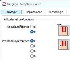 |
This may happen if the Graphic Card in charge is the Integrated graphics! We advise you to switch to your high-performance graphics, Nvidia or other. Method 1: you can choose the default graphics for all the applications at once,
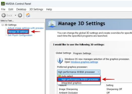 Method 2: you can select the graphics for each application, one by one.
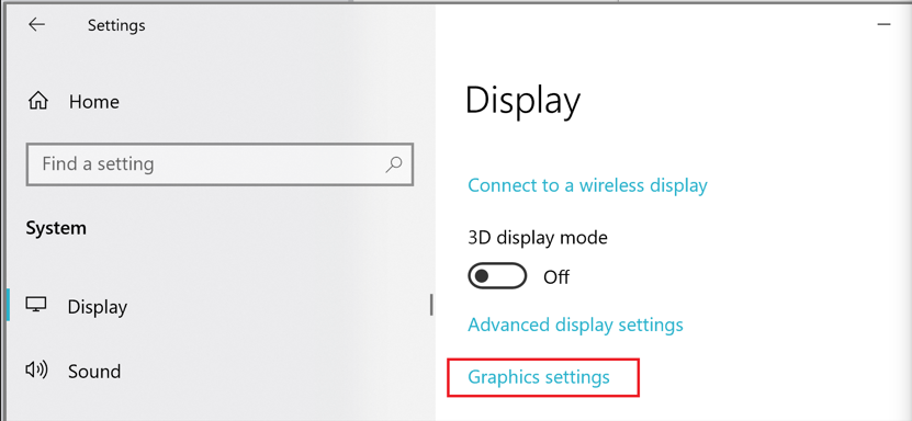 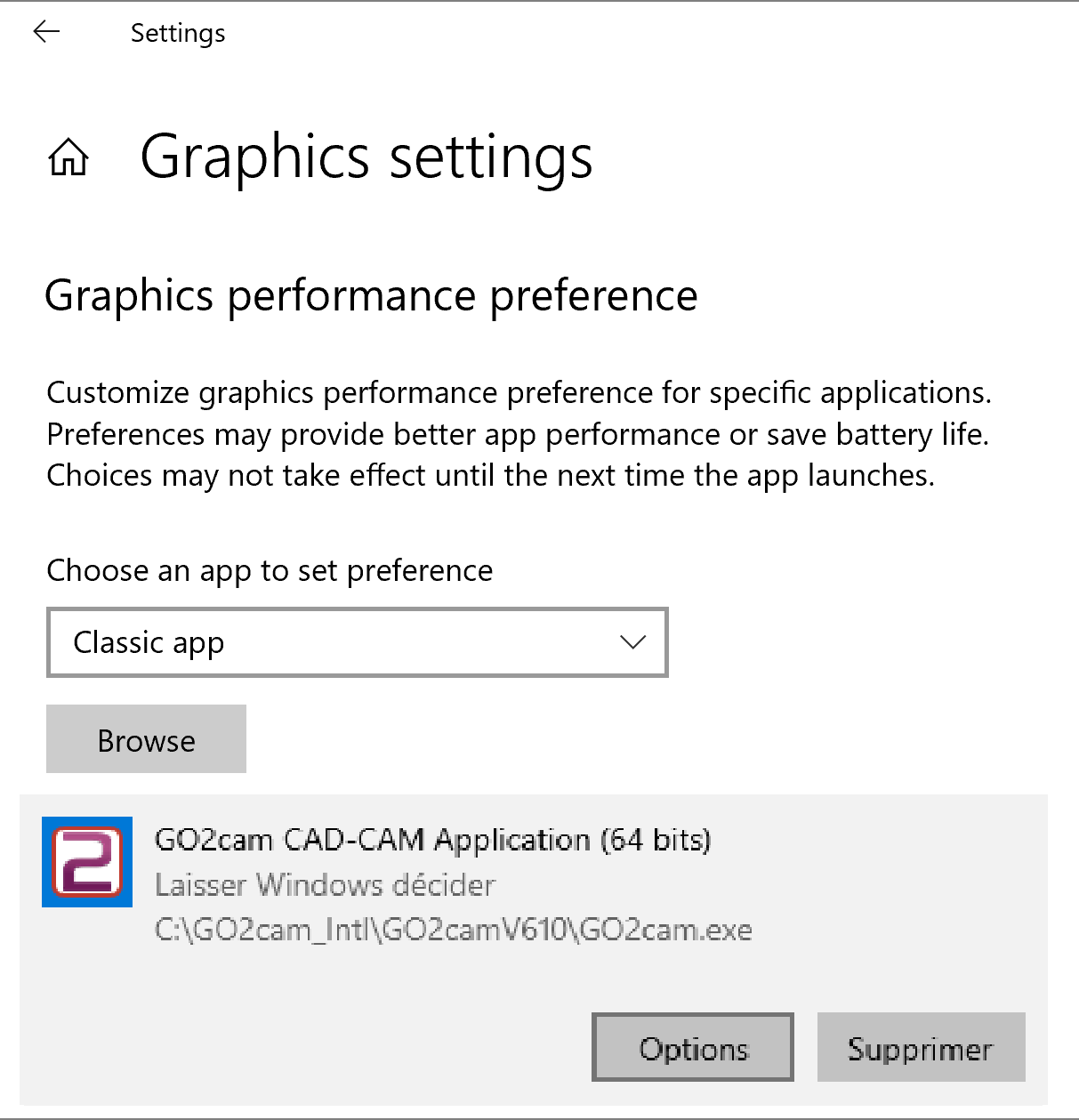
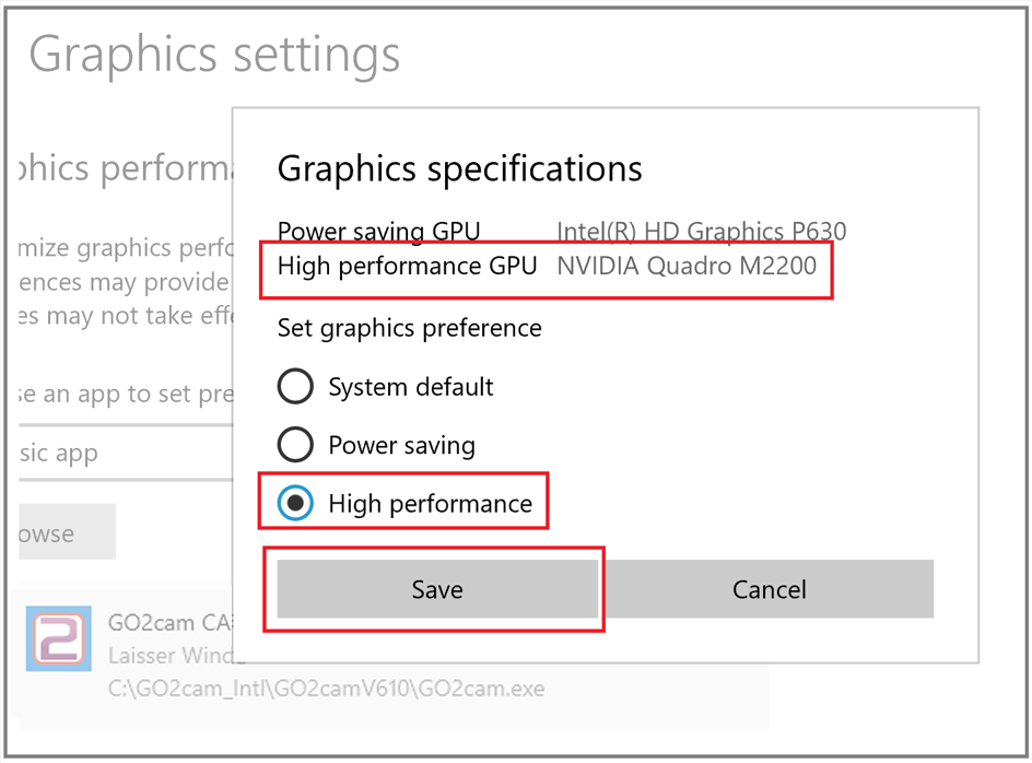 | |
During simulation, the holes are not precise, showing a hexagon instead of a circle. | |
We have two ways of controlling the precision during the simulation:
| 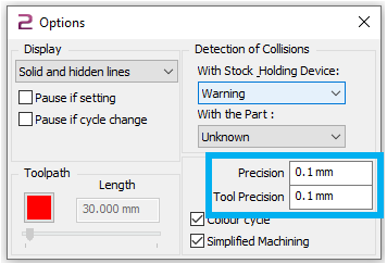 |
Here, we have a component with a tolerance of 0.1 mm is shown on the basis of the display tolerance. The blue 2D circle is included as a comparison, so that the calculation of the solid model display in the form of the circle approximation by line segments is very well recognizable. | 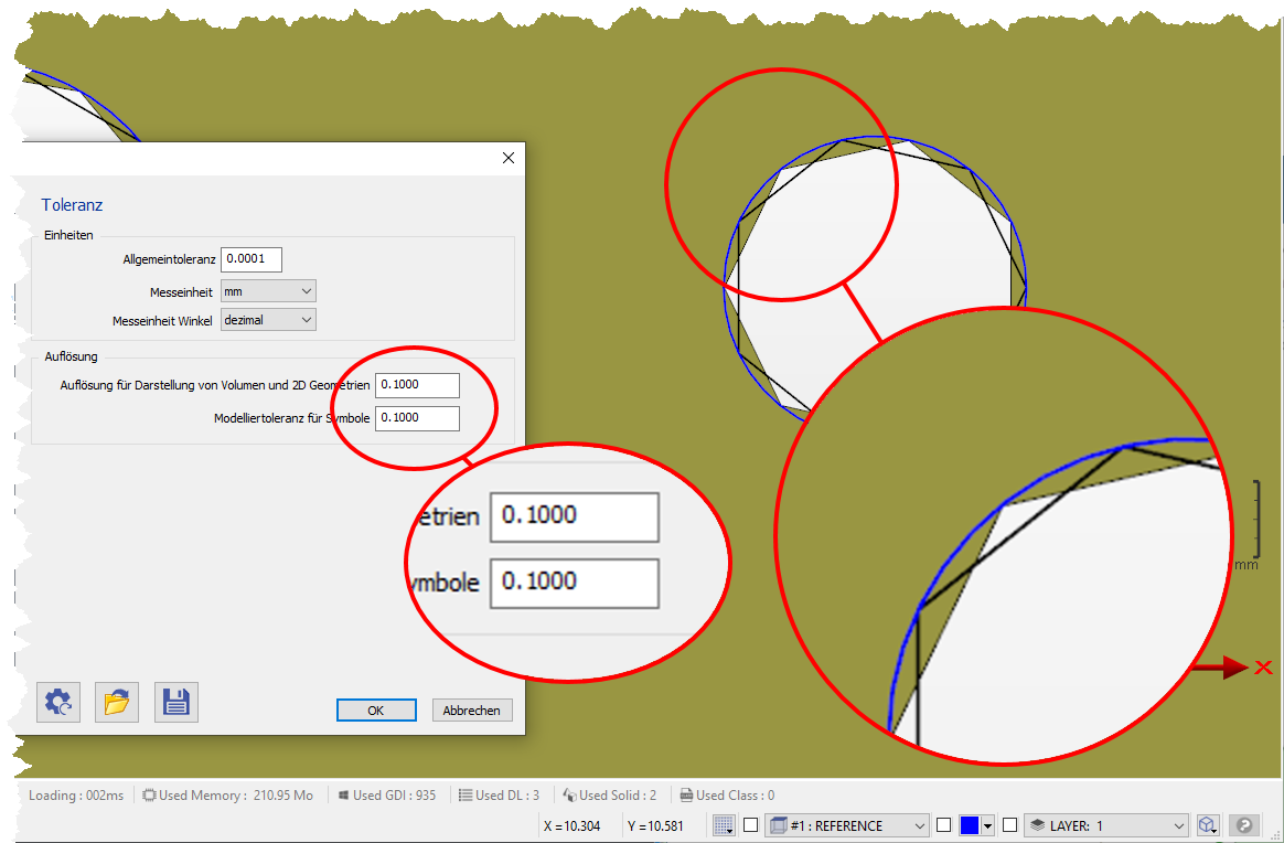 |
By changing the precision to 0.01 mm for both the precision and the tool precision, you will achieve a smoother circle representation. Whether you choose a coarse 0.1 or finer 0.01 tolerance is something you have to decide for yourself in the context of the current component size. The finer the tolerance, the longer the simulation times. | 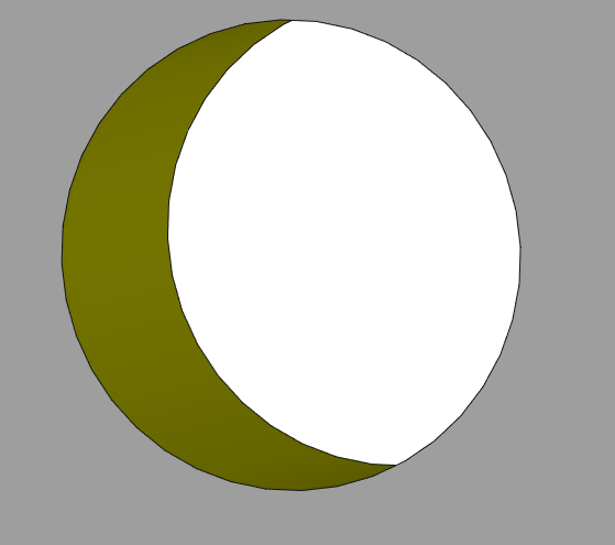 |
When I update to GO2cam V6.10, I cannot use neither the menus and toolbar I customized in my previous version! | ||
| ||
Name in V6.09 | Name in V6.10 | Corresponds to… |
TBR_SPD0.USR | tbr_product_mill_classic.usr | Mill Classic |
TBR_SPD2.USR | tbr_product_edm_classic.usr | Wire EDM Classic |
TBR_SPD3.USR | tbr_product_turnmill_classic.usr | Turnmill + C Axis / Turnmill Classic |
TBR_SPD4.USR | tbr_product_mill_expert.usr | Mill Expert |
TBR_SPD5.USR | tbr_product_document_model.usr | User Workshop Document |
TBR_SPD6.USR | tbr_product_drawing.usr | Layout Design |
TBR_SPD12.USR | tbr_product_turnmill_expert.usr | Turnmill Expert |
TBR_SPD16.USR | tbr_product_andrea.usr | Mill Classic + Boring Head |
TBR_SPD17.USR | tbr_product_swissturn_classic.usr | Swiss Machining Classic |
TBR_SPD18.USR | tbr_product_swissturn_expert.usr | Swiss Machining Expert |
More information are given in the page about Customize Menus and Customize Toolbar
I have only one machine, can I have it always loaded in GO2cam? |
Yes, it is possible. For this, go to Tools>Options>Machining, and you will be able to choose a machine file as the default machine. Each time you will enter GO2cam, the machine file will already loaded. You can do exactly the same with a material file for the cutting conditions. |
I import a CAD file of 5Mo, but after working in GO2cam and saving the file, it exceeds 200 Mo, Why? Can I reduce the size of the *.PCE file? |
Most of time, the size of the *.PCE file is in relation with the 3D bodies of the part and especially the stock. The polyhedron of stock is archived at each step of machining and if the stock is a little complex and contains multiple faces, the size of file can increase very rapidly! To face this situation, an option enables to set a different type of calculation, by deleting the step polyhedrons and keeping only the last one. Go to Tools/Options, then page ‘Save’: 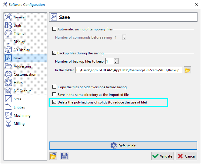 |
