
|
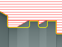
When I program a roughing or a finishing operation, I would like to avoid plunges into grooves!
|
|
|
You can do it with an option of the Strategy page called Undercut.
More information and a video are given here: Undercut |
|
|
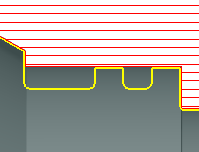
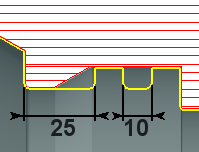
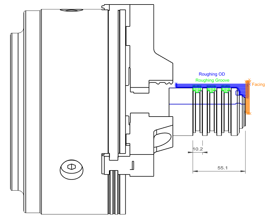
How to program a finishing with a back toolpath, that avoid grooves and does the Facing Operation?
|
|
|
Please watch the video that shows all the steps of this process: Click the link to get more information about Machining allowances |
|
|
How to transfer a workpiece from Milling to Turning?
|
|
|
Here are the steps to transfer a part programmed in milling into the turning environment. Please watch carefully the video to respect the process; here we use MTE but the process is the same without MTE. |
|
|
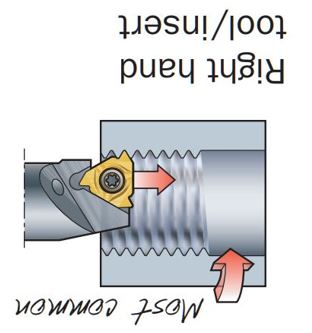
How to program thread turning?
|
||||||
|
|
||||||
|
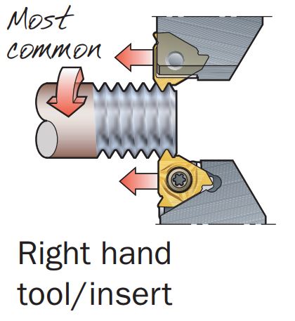
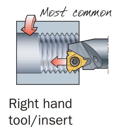
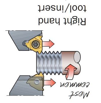
From the Sandvik User's Guide |
||||||
|
Right-hand thread viewed on the Main Spindle |
Right-hand thread viewed on the Sub spindle view (Rotated by 180 degrees) |
|||||
|
|
|
|
|||
|
Table Thread Type / Wkz. / Machining Direction / Direction of Rotation |
||||||
|
Thread Type |
Tool |
Forcibly coupled |
Direction of rotation |
NC |
Feed direction |
|
|
Right-hand thread |
Right |
↔️ |
CCW |
(M3) |
sliding (to lining) |
|
|
Right-hand thread |
Left |
↔️ |
CW |
(M4) |
pulling (away from the lining) |
|
|
Left-hand thread |
Left |
↔️ |
CW |
(M4) |
sliding (to the lining) |
|
|
Left-hand thread |
Right |
↔️ |
CCW |
(M3) |
pulling (away from the lining) |
|
|
CW & CCW: is defined to be understood in such a way that the user looks at the chuck from the direction of the tool and the direction of rotation results from this.
|
||||||
|
Summarizing:
|
||||||
|
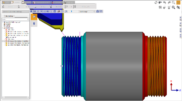
This results in the following image for GO2cam Right-hand thread on the outside with left tool
Only possible with dragging machining due to the CW.
If you simulate this editing in GO2cam version < 6.08.202 on the Sub Spindle, the wrong direction of rotation seems to be simulated, so that the visual result shows the wrong slope slope. |
|
|||||
|
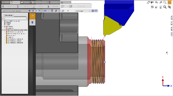
Right-hand thread on the outside with the right tool Only possible with sliding machining due to CCW. |
|
|||||
|
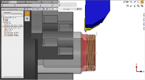
Right-hand thread inside with the right tool Only possible with sliding machining due to CCW |
|
|||||
|
Thread Parameters The choice of parameters for thread turning also depends on the tool, as the following example illustrates: In the SinuTrain programming station from SIEMENS, the thread cycle CYCLE97 is used to produce an external thread with a pitch of 1. A thread depth of 0.5mm is used (i.e. 1mm in diameter) so that the result is easily verifiable in the simulation. Thread tool defined with the "correct" cutting radius of 0.1443mm according to DIN 13. |
||||||
|
Parameters: hn = Overall depth
|
Thread tool defined with a standard cutting radius of: 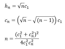
|
|||||
|
Therefore, the first and last infeed must be selected according to the desired total depth and the number of roughing cuts (and vice versa). If the post-processor used outputs the thread processing as a machine cycle (e.g. CYCLE97 for SIEMENS or G76 for Fanuc), the essential parameters are the thread pitch, the total depth and the number of (roughing) cuts. In this case, the NC code is correct in any case. An incorrect combination of parameters can lead to incorrect simulation of thread machining. If the post-processor used does not output a machine cycle, but the individual cuts with G33, the NC code is also incorrect in this case! |
||||||
|
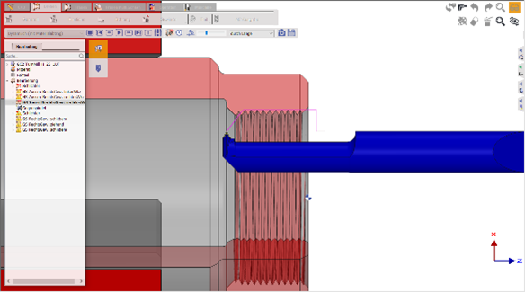
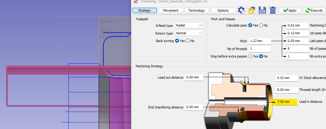
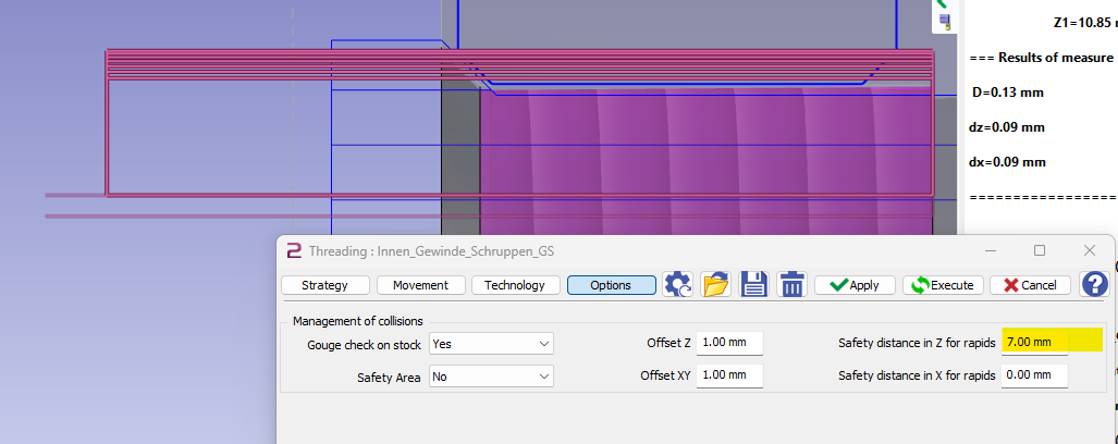
For the internal threading, I want a greater safety than in the operation.
|
|
|
The Z position between the passes is managed by the selected geometry.
|
|
|
As the geometry has a lead in distance, the toolpath manages the Z retract 7 mm from the start of the geometry element. |
|
|
To have a retract at the end which is more than during the operation you can set a value in the Safety distance in Z for rapids. |
|
|
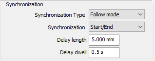
How to define MTE settings for machining cycles synchronization?
|
|
|
For machines with multiple turrets, the ability to synchronize various cycles improves the efficiency of the machining process by reducing idling of tools and overlapping the machining times of each cycle without any collisions. In GO2cam, to define synchronization between 2 cycles, you can follow the steps below: |
|
|
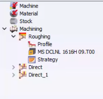
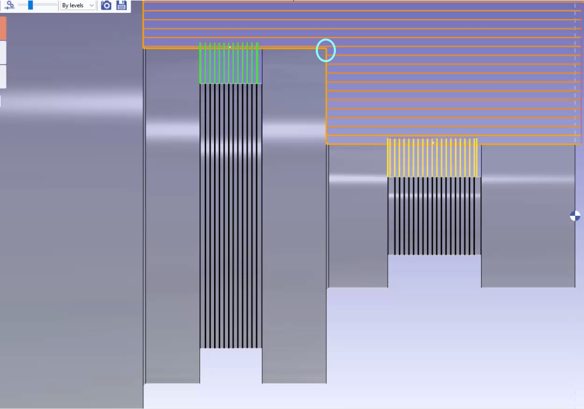
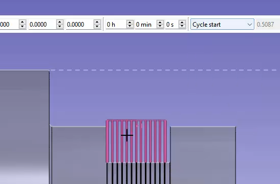
Define your machining cycles as usual with separate tools.
For instance in this example, we would like to synchronize the Direct_1 grooving cycle(green toolpaths) with the roughing cycle at the indicated point (as encircled). The aim is to start the grooving cycle just as the roughing cycle reaches the encircled point. |
|
|
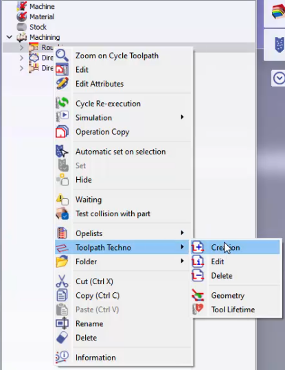
To do that, right-click on the required cycle, in this case the roughing cycle and choose creation from the Toolpath Techno selection.
|
|
|
Choose Toolpath Synchro from the drop down list. 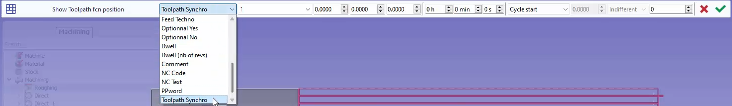
|
|
|
Then you can choose the toolpath parameters to define the entity to synchronize, Click on ok e=and validate. 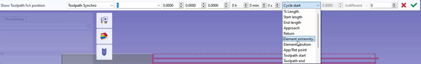
For this example, we will select the Element extremity and click on the toolpath line that touches the encircled region(in the previous photo). |
|
|
We repeat the same thing for the grooving cycle(Direct_1). For the toolpath parameter we choose Cycle start and select the grooving toolpaths. |
|
|
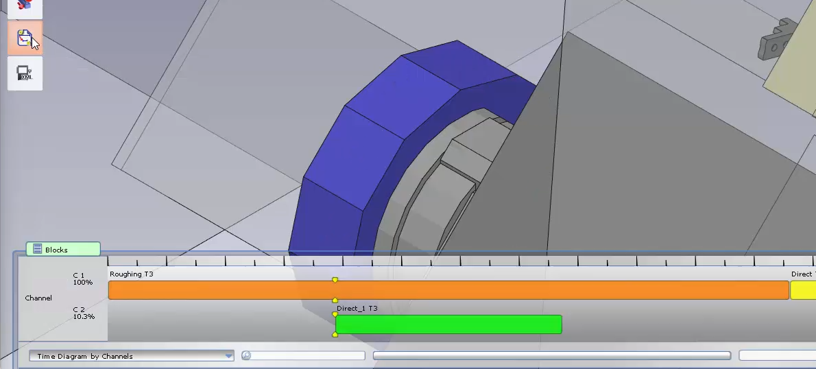
Next, moving on to the Machine environment, you can load your machine if you haven’t done so and set up your Tooling as required. Finally you can check your synchronization by clicking on the synchronization function. You will be able to see the synchronization between the cycles on the Time Diagram. |
|
|
▶️ You can watch a video of the example with some additional details below:
|
|
|
How can I layout a turning part and its components?
|
|
|
For turning, under the NC File menu, we have the option Transfer to Layout/Dimensioning in the collapse section. Your machine should be loaded with the symbols: Chuck and Jaws. You must ensure that the symbols are from the sym folder found in the GO2cam directory. In some cases, it may be outside of this folder and GO2cam will prompt a warning. Simply copy the files in the sym folder: C:\GO2cam_Intl\GO2camV6XX\sym |
|
|
When clicking on the icon, a dialog will appear: The dialog allows you to:
Select the cycles you wish to layout and click on the green tick to validate. GO2cam will open saves as dialog to save the file, before changing environment. |
|
|
In the Layout Design / Dimensioning, you can start drawing the layout. |
|
|
How can I program inside roughing using a radial toolpath?
|
|
|
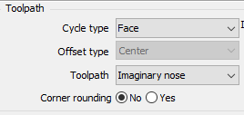
To achieve inside roughing with a radial toolpath, follow these steps:
|
|
Watch a video on the right explaining the process. |
|
|
How can I create a toolpath manually in GO2cam?
|
|
|
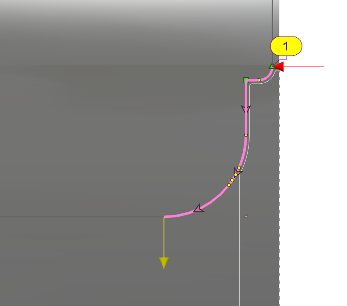
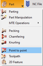
Being able to define a toolpath manually is of utmost importance, especially in the application of specific forming tools. Such tools have distinct cutting shapes and their cutting path has to be carefully controlled to avoid the risk of collisions. The cycle Point to point helps achieve this. It is accessible under the Part submenu. |
|
|
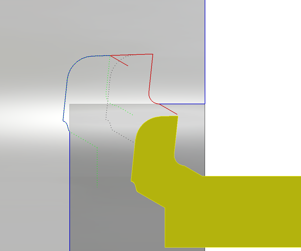
The Point to point cycle is a 100% manual cycle with minimal parameters. It is used to generate specific toolpaths unable to be defined by other cycles. As such the method of geometry selection may also slightly differ. For instance in the example below, to machine the internal shape with this specific tool shape a guide profile (in red) has been drawn, to assist in the geometry selection especially for angular motions to avoid collision.
Note: The guide is not compulsory, in other cases, the required toolpath can simply be defined from the part profile and approach/return points. |
|
|
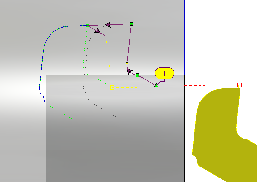
Select the guide to define the profile. Define the Approach point path. (in red) Define the Return point path. (in yellow) The approach point, together with the profile selected and the return point define the whole motion of the piloted point of the tool. Choose the tool and the cycle(cycle type should be internal) and run the calculation. This will generate the toolpath to machine this profile. For this cycle, stock calculation is not carried out. Also there is no collision check between the part and tool.
You can watch a video on the right showing this example. |
|
|
|
|
MTE: How can I have 2 different tools in a synchronized cycle?
|
||
|
Define your Balanced Roughing/ Balanced Finishing cycle as usual with the required synchronization settings. In this case, since a single tool has been chosen, the same tool will be loaded twice in MTE. 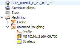
|
|
|
|
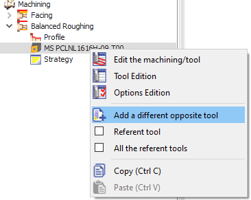
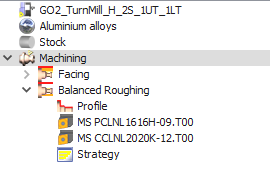
To be able to set a different second tool, expand the cycle in the machining tree. Right-click on the existing tool select 'Add a different opposite tool'. This will open the tool selection window again where you can choose the tool you require and validate. Both tools will be visible in the machining tree now. In MTE, if you do Auto mount, these 2 tools will automatically be mounted on opposite turrets. |
|
|
|
You can watch a video explaining the application of the balanced synchronized cycles. Skip to 2.20 in the video to view the definition of 2 different tools for the cycle. |

|
|
|
How does the "Deburring Length" parameter work? |
|
|
The "Deburring Length" parameter works by determining the distance the tool moves in the Z direction to cut the chip on the bar. This distance includes the tool radius.
|
|

|
|