

|

|

|

|
The simulation of machining is an important step in the cadcam programming. It enables to control and validate the machining process, to detect programming errors and to check possible collisions with machine environment and toolholders. |
Presentation
Types of simulation
Several types of simulation are available:
-
Dynamic mode: this simulation includes material removal.
-
Toolpath mode: own internal simulation, no material removal.
-
Faster 3D mode (Milling only) : special option dedicated to 3 Axis milling cycles. This simulation is faster, the result obtained is more important than the toolpath done. Warning, this simulation is only available for cycles done on the reference plane.
Dynamic and Faster 3D simulations are issued from the same component, developed by MachineWorks Ltd.
Access
The simulation is accessible in the menu NC File
|
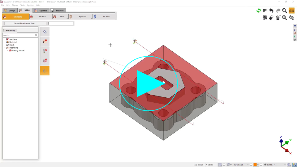
▶️ You can watch a video showing this action: |
|
How to run the simulation
2 methods are possible to launch the simulation:
|

|
Click on the ‘Play’ icon will run the simulation continuously. |
|

|
Click this icon to launch the step by step mode. You can also press the SPACE key on the keyboard. |
Simulation Options

|
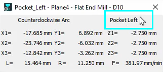
Coordinates: click on this button to display the coordinates of the points of the toolpath simulated. Some other interesting information are also given:
|
|
||

|
|
|||

|
Options: adjustment of the display, the detection of collisions and the precision, images creation etc. |
|||
|
In Dynamic simulation:
|
||||

|
Analysis of collisions (only in Dynamic and Faster 3D). |
|||

|

|
Show/Hide the extra functions which are different for each of the simulations available. |
||

|
Control the simulation speed with the cursor. Click this icon to reset to default speed. |
|||
|
Option |
Different modes of toolpath visualization are offered; the color of toolpath is defined in the dialog Options. |
|||
|
In simulation ‘Toolpath’:
|
In simulation ‘Dynamic’:
|
|||

|
Creation of an image of the simulation at any moment. the image is saved in the directory IMG. Four types of format files are offered: *.BMP, *.JPG, *.PNG, *.TIF (only in Dynamic and Faster 3D). |
|||

|
Creation of STL file: the stock at t time is created and exported in the file format *.STL. The file is saved in the directory Ascii (only in Dynamic and Faster 3D). |
|||

|
|
|
We can now edit any cycle while running the simulation, simply by double-clicking it in the machining Tree.
Tapping operation: we can simulate the tapping steps while setting OFF the ‘Simplified Machining’.
|
▶️ You can watch a video on Coordinates of Deburring & Chip-breaking in Simulation: 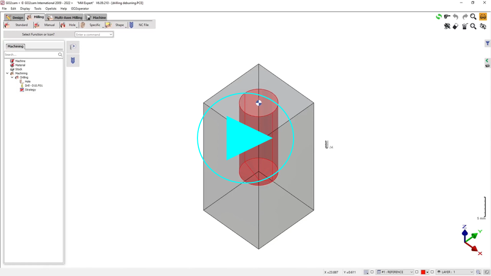
|
▶️ You can watch a video on Pause if cycle Break and Tapping steps:

|
Wire-EDM Simulation: in dynamic mode, the simulation is not precise but only informative:
-
the trace in the stock is not calculated according to the wire diameter and the electric sparkle,
-
the position of the wire is not given: we simulate in center of wire. This is why we indicated the position with a purple arrow.
-
at the end of simulation, a removal of material is shown; to determine the type of machining (die or punch), you first need to select the right settings in the dialog box of Options.