Standard Holes
Presentation
 | Creation of a normalized hole defining its type, its diameter and its depth. An operation list is automatically defined for machining. |
Notes:
| ||
Holes Editor: useful to change the type of hole or its values. Edit element (Ctrl-H) on a hole enables you to modify its position only. | ||
| ||
 | Transformation into hole | |
 | Solid Hole Recognition | |
Radial Hole | ||
Axial Hole | ||
Hole on a slope | ||
Creation of Standard Hole
The creation of a standard hole is described in 3 stages :
1. Definition of standard hole
2. Optional: creation of Favorites and Customization of List of Operations
3. Positioning of the hole in the design
1. Definition of standard hole
The dialogue is divided into 3 tabs:
Holes Models: definition of topology and sizes
a. Choose the type of hole in the dialogue zone: | ||
 | Blind smoothed hole | 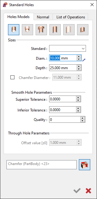 |
 | Blind tapped hole | |
 | Through counter bored hole | |
 | Through smoothed hole | |
 | Through tapped hole | |
 | Smooth hole with flat bottom | |
b. Define or not a chamfer on top of the hole. | ||
To define a chamfer, activate the checkbox for Chamfer Diameter and insert the diameter value. | ||
c. If the hole is standardized, fill the Standard field (e.g: M6). | ||
If you have to define a standardized hole such as an M10, for most of the models, you can access a drop-down list in the Standard field with the various models. Select the required one and the parameters will be updated automatically. | 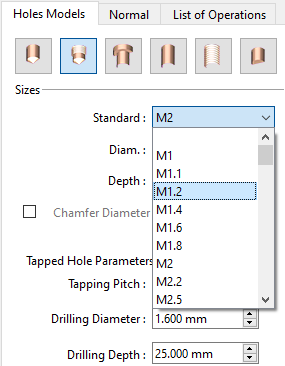 | |
d. Setting complementary parameters | ||
Complementary parameters are available under the Parameters section ( name varies with the type of hole chosen). The parameters regarding the type of hole defined, such as the tapping pitch and the diameter and depth of a counter bored operation are accessible here. For standardized Holes, the values are automatically filled and come from GO2cam standard files, Standard.csv for tapped and counter bored holes and Tol.csv for Reamed holes. | 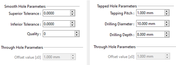 | |
You can define your own standard files in the csv format and save them in the directory GO2cam\Holenor. Then declare them in Tools/Options/Holes. We advise you to base your files on the default files to respect the syntax. | 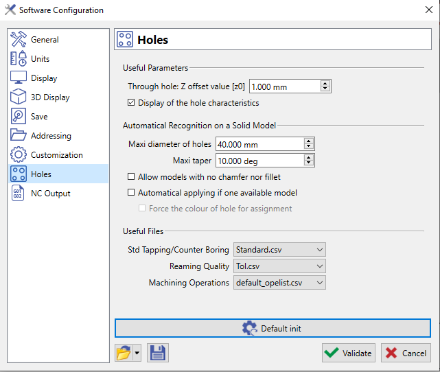 | |
Normal Tab: direction of the holes
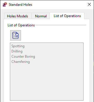
List of Operations
A list of operations is automatically associated to Standard holes regarding the type and the characteristics of the hole. This list is greyed out because you cannot modify it; they are only information at that stage. Note :
|
You can find some examples in the section below : Standard Holes Examples
2. Optional actions:
These 2 options are only available with the HMF package!
a. Favorites
b. Customize the list of operations
 | This command provides the means to adjust the operations in the list and to modify their parameters. Click here to know how to manage and modify the List of Operations |
3. Positioning of the hole
a. If needed, enter the altitude (Z value) corresponding to the top of the hole.
b. Define the position of the hole : Click on a point or enter its coordinates in the dialogue zone.
Machining : go to Milling, Hole menu, then choose Automatic and follow the next stages.
Standard Holes Examples
1. Counter Bored Hole for a M10 Screw
Choose Through counter bored hole |  |
Check the box for Chamfering. | |
Choose M10 in the standard field : the diameter field is for the drilling diameter ; it is automatically filled (10.5 mm). The depth has no importance, counter bored hole are always through material. | |
Click the parameters dialog; the counter boring diameter (20.4 mm) and height (10.5 mm) are automatically defined, so is the chamfer diameter (11.55 mm). | |
You can modify these values if you want. Now simply click to place the hole on the screen. | 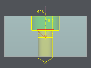 |
2. Blind Tapped Hole M14
Choose Blind tapped hole |  |
Check the box for Chamfering. | |
Choose M14 in the standard field : the diameter field is for the tapping diameter ; it is automatically filled (14 mm). Enter a value for the tapping depth (example 27 mm) | |
Under the parameters dialog; the Tapping pitch (2.0) , the drilling diameter (12 mm) and the chamfer diameter (15.40 mm) are automatically defined. Finally, the drilling depth must be defined by the user. If it is not correct according to the tapping depth, an error message is displayed at the bottom of dialog. | |
You can modify these values if you want. Now simply click the position where to place the hole on the screen. | 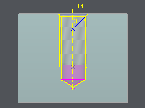 |


