Vice with a Single Mobile Jaw
Introduction
This page explains how to create a vice with one mobile jaw for a mill machine.
▶️ You can watch a video at the bottom of page: Click here |
Creation of vice
Select the “Clamping / Toolholders” module in the Homepage. | 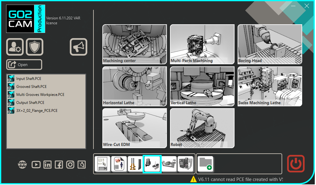 |
Click the GO button |  |
Select the file to import | 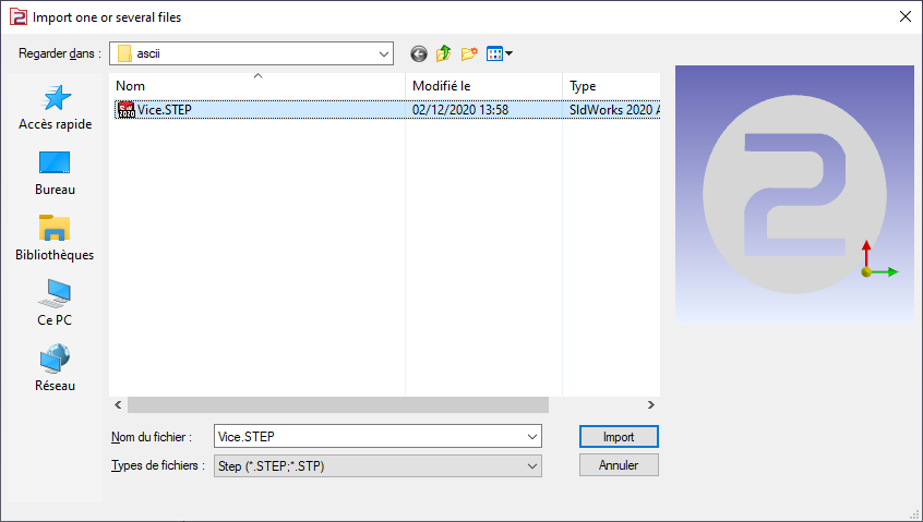 |
Choose the import option you want to apply on the solid. Click “Apply” | 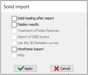 |
Click the plane face to orientate the vice. The clicking face will have Z axis as normal vector. | 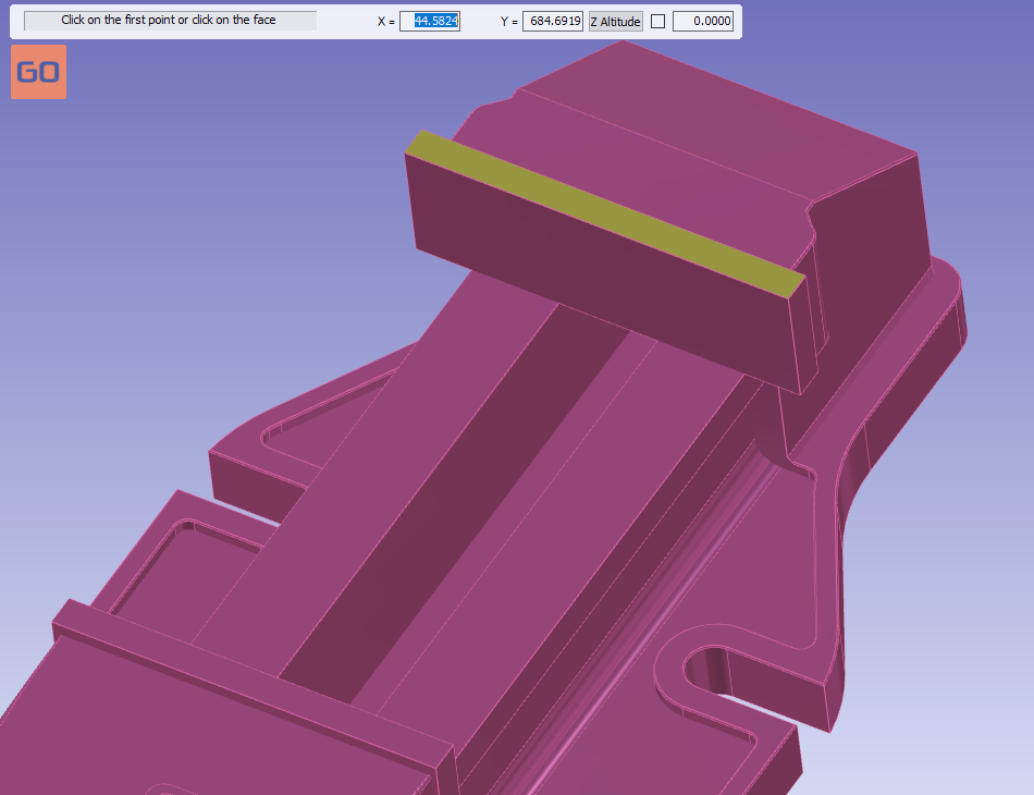 |
The origin can be directly validated without anymore action. | 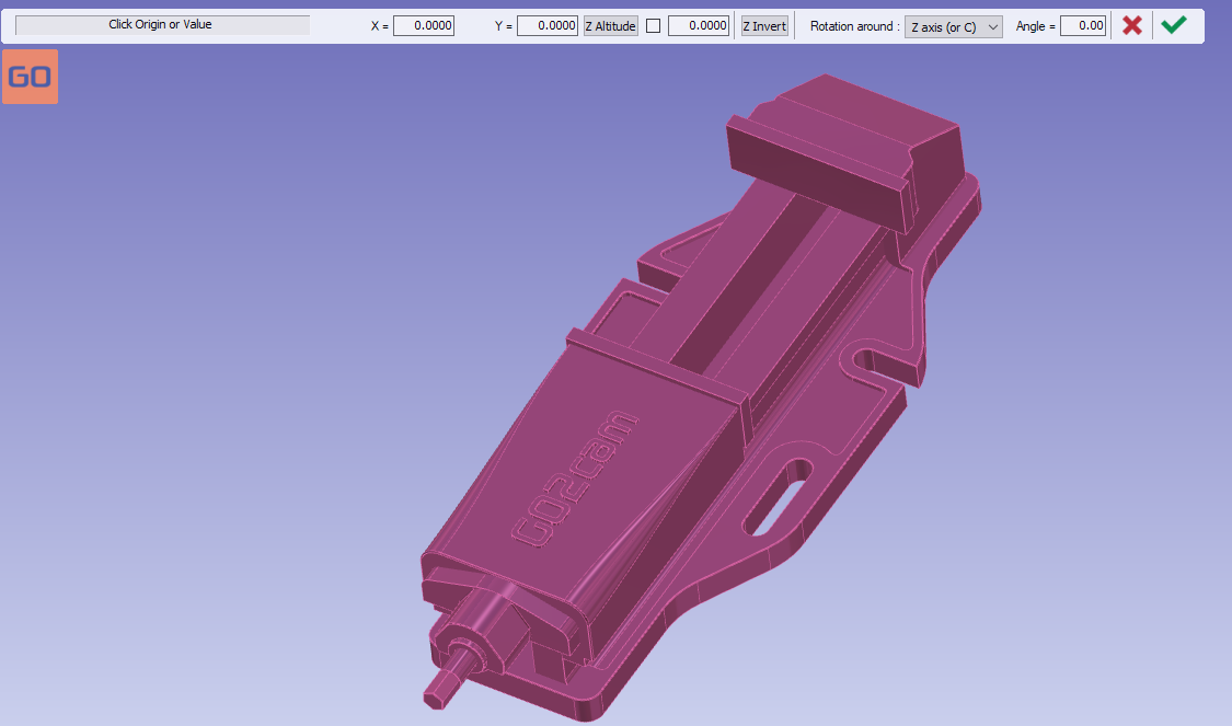 |
Click on the tab “Creation” then “vice and Clamps” menu | 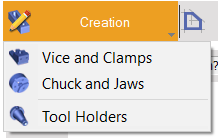 |
Click the command to create system of axis |  |
Select the tool to define the position of system of axis |  |
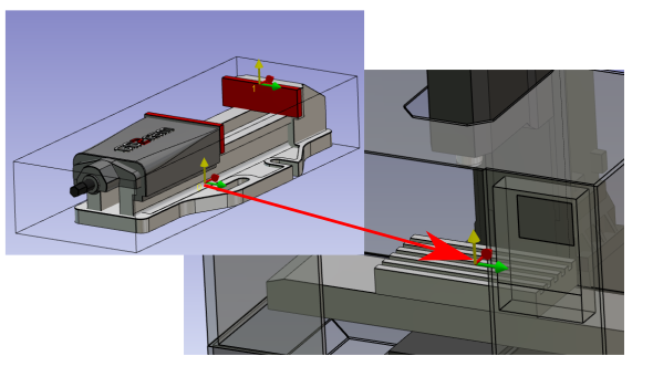
Define the system of axis 0. The system of axis will match with the system of axis, of work assembly support, where the vice will be mounted. | 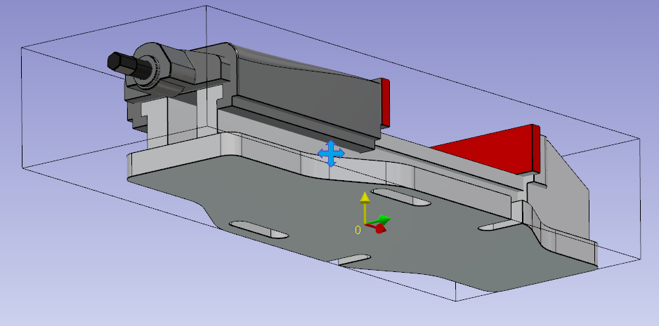 |
Do the same command to create the system of axis 1. The system of axis 1 will be the point you can drive when you set the position of the vice on the part. | 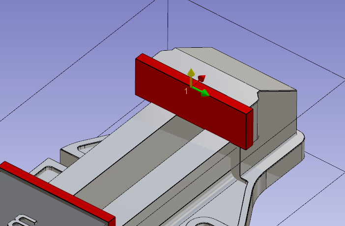 |
Click on the component vectors tool. |  |
You are invited to select mobile element. All the geometry not selected in mobile element will be consider as fixed element. | 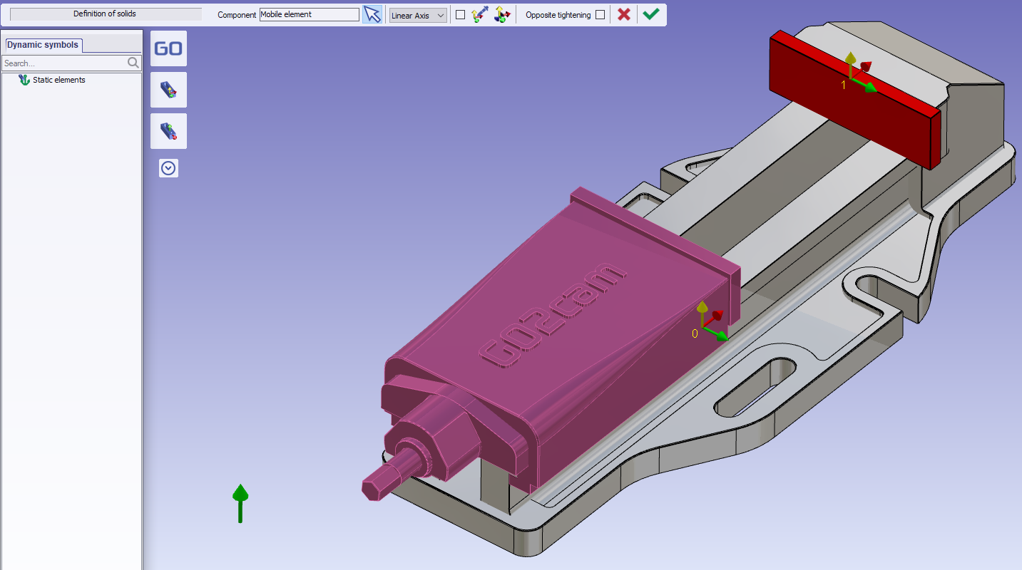 |
The click the tool to create direction of movement |  |
Click the face of mobile jaw | 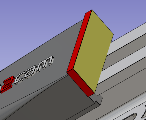 |
Validate the mobile element creation | 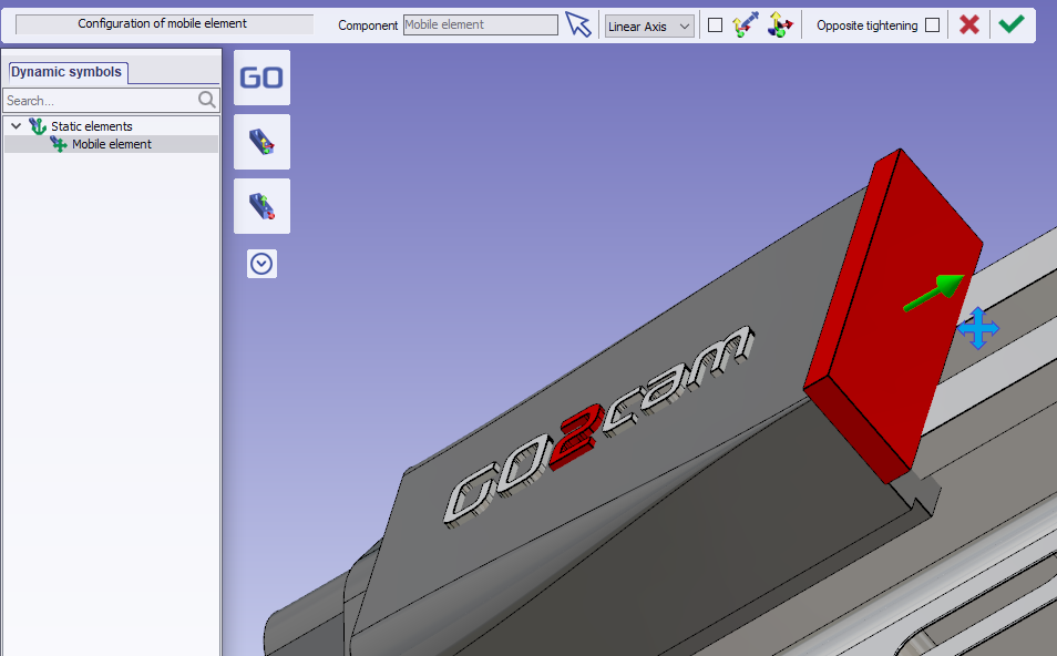 |
Save the file in your symbol folder to use it in GO2cam. | 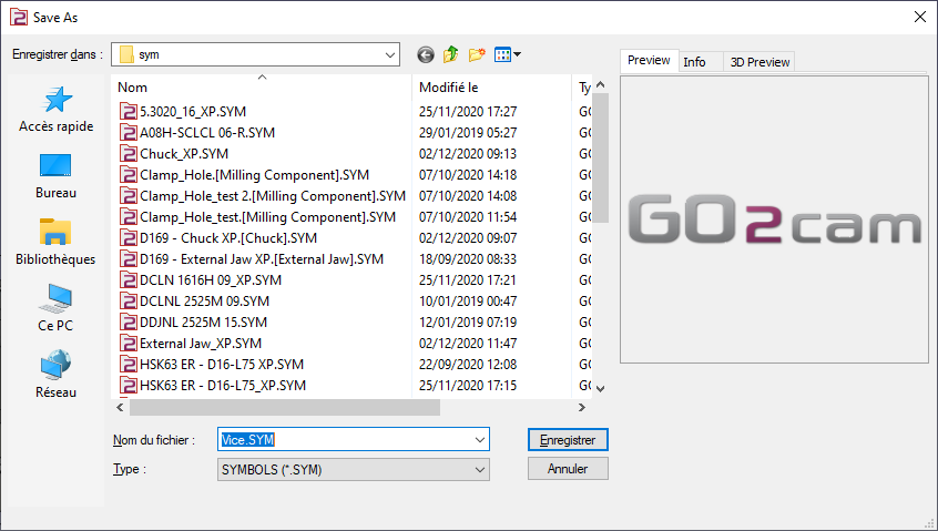 |
Key points
The system of axis 0 will be mounted on the work assembly support of the machine.
The system of axis 1 will be used to position the vice on the stock.
You can define more than one system of axis to position the vice on the stock. To do, add system of axis.
