
Introduction
This method enables to calculate all the islands at a given altitude by taking the stock as the pocket.
At first sight, the result obtained could pass for a section, but this is not : the calculation takes into account all the material that is over the given altitude. Therefore it manages undercut shapes and as it is calculated from the stock, it also manages the multi-faces machining.
Characteristics:
1. Bottom radius:
As any other type of profile, if there is a radius on the bottom of the pocket, the profile is created shifted from the radius value.
A symbol points out the presence of a radius on the bottom and the value is displayed in the label.
The bottom radius may serve solely as a visual feature without any mechanical function. To exclude it from machining, the Reading on Solid option must be set to No in the Options page of each cycle. If set to Yes, the cycle will machine the radius while maintaining the crest value specified in the Options page.
2. The stock is the pocket:
The leadin of the tool will be always outside of the material. What is created by the silhouette profile are the islands, in other words the material which is not machined.
3. Altitude of selection:
Multiple silhouette calculations can be performed, as each will vary depending on the selected calculation altitude.
Advice:
This type of profile is dedicated to facing and contour roughing operations.
It will not be efficient to machine closed pockets, or any interior shape.
Methodology
-
Right-click to select Silhouette
-
Click a face to give the orientation of the tool.
-
Give the altitude of calculation (bottom Z)
Examples
|
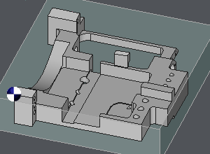
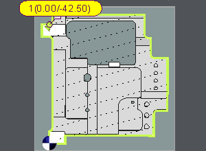
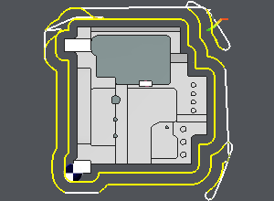
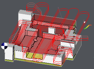
Contour Roughing Click any flat face on this part. To be sure to get the whole part silhouette and program a contour roughing, select the lowest Z. What is calculated is the material avoided during machining, the stock is the pocket. |
|
|
|
|
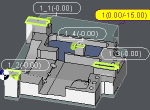
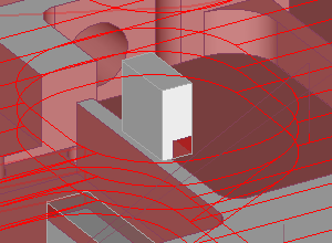
Facing Roughing In this case, only a roughing operation is to be performed from Z0 to Z-15. A flat face is selected, and the Z value is defined either by direct input or by referencing a solid edge. All islands to be avoided are automatically calculated and positioned at Z0. As illustrated in the third image, island number 4 features an undercut shape. The profile is accurately generated to accommodate this geometry. |
|
|
|