
|
|
The auto mounting system in GO2cam intelligently manages the placement of tools on both the spindle and turret, streamlining setup and optimizing machining efficiency. |
How It Works:
|
On launching the function, a ribbon appears with three checkboxes for reset of turret numbers, reset of tool numbers and force the gauge Y=0. It is generally recommended to check these boxes to reset these parameters so as to avoid any previous settings saved in the software and ensure proper tool mounting.
Watch a video on the right showing a quick auto mounting process. |


|
|
For tools without predefined mounting positions or constraints, GO2cam allocates them to available slots according to the order of operations. Tools that have specific tool numbers or location requirements are mounted accordingly, with strict enforcement of any constraints defined during tool creation. This logic applies to both spindles and turrets:
|
|
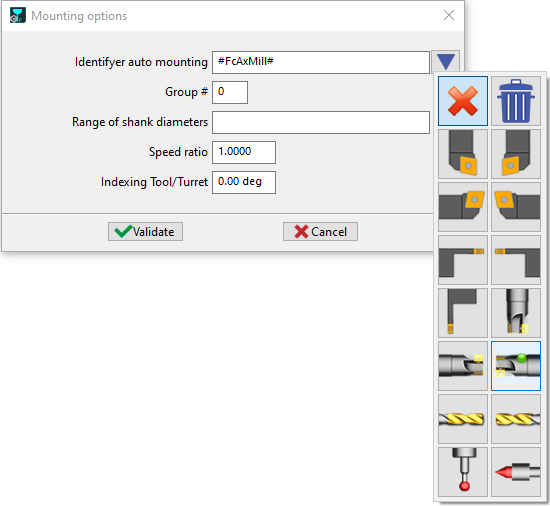
Rules for Auto-Mounting Tools Based on Diameter Range and Tool Family
|
To improve automatic tool mounting during machine changes, a diameter range system has been implemented in addition to the existing tool family compatibility. This applies only to rotating tools, as the shank diameter determines whether a tool can be mounted on a holder. Step-by-Step Process for Auto-Mounting
1. Define Diameter Ranges on Machine Tool Holders
If no range is specified, the holder is considered unrestricted (compatible with all diameters for backward compatibility) |
|
|
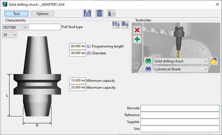
2. Define Diameter Ranges on Tool Holders (Symbol)
3. Configure Standard Tool Holders (Predefined in GO2cam)
|
|
|
4. Automatic Mounting (Tooling Setup)
Tools already assigned to a holder will not be remounted. To reassign, first unmount the tool manually. |
|
|
Watch a video on the right showing the setups prior to a proper and repeatable automounting. |

|
Tool Mounting in Swiss Machining – Useful Length Selection
A tool group can be configured with a maximum useful length parameter. Additionally, each individual tool may define its own maximum useful length.
During automatic mounting or manual drag-and-drop mounting operations, the system determines the applicable useful length by referencing a designated tool. If no reference tool is specified, the machine's default useful length setting is applied.