
Introduction
|
|
This menu is used to configure the machine environment in order to enable machining simulation.
When you click on the Tooling menu, the user will be prompted to set up the tool. |
|
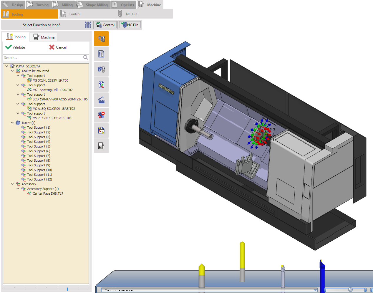
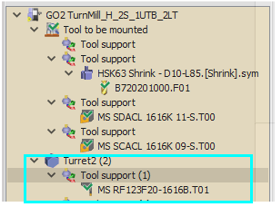
The Tool Tree displays all tools required for the machining process. Under “Tool to be mounted”, you will find tools that are currently unmounted. Under “Magazine Spindle/ Turret”, you will see the machine’s tool magazine, which lists tools that are already mounted. To mount a tool, drag and drop it from its Tool Support location to the appropriate Pocket in the magazine. Insert a tool holder for each of the tools if they haven’t yet been defined. The Machine sub-tab shows the setup of the machine. The selected pocket must correspond to the actual pocket on the physical machine to ensure the tool number matches the one used in the NC program. |
|
Tooling User Interface & Manipulations
|
||
|
|
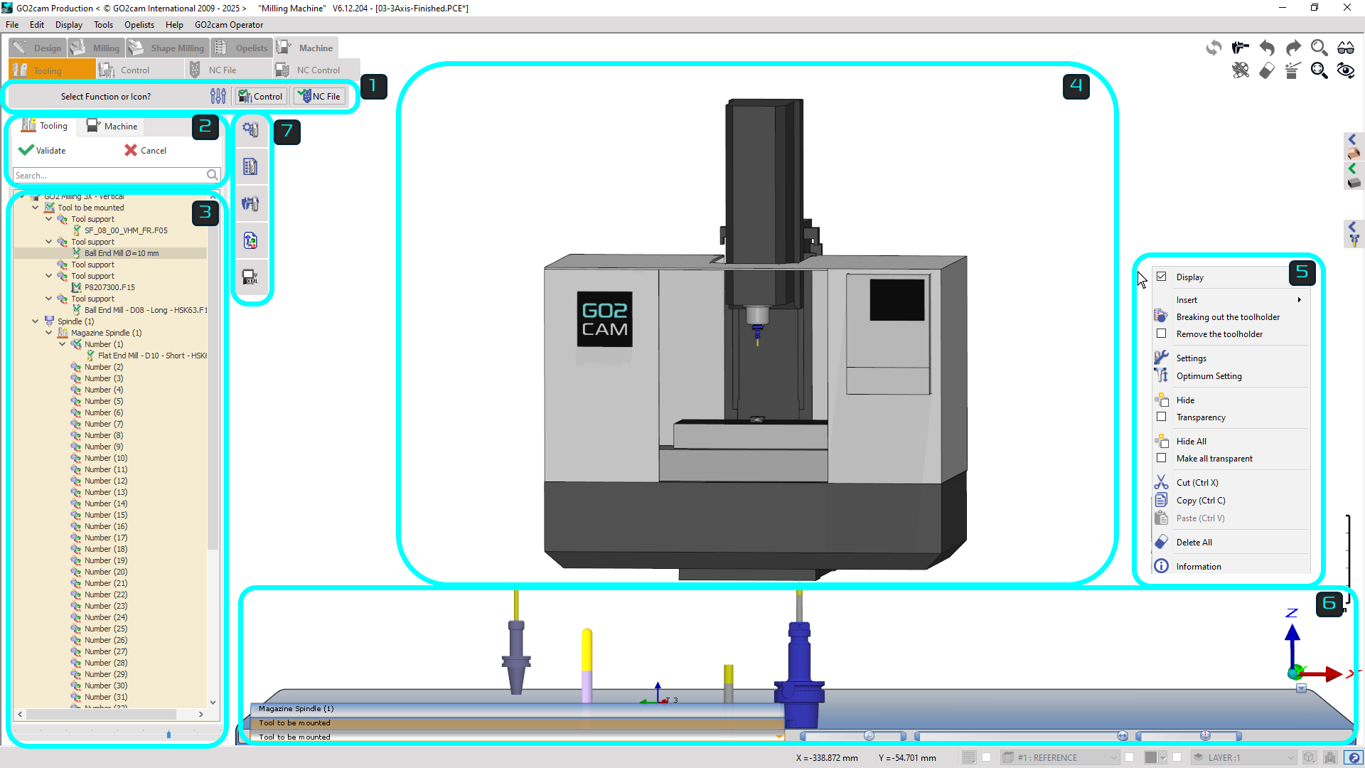
Ribbon: Provides settings for the graphics display, collision detection, validate and move to the control menu and validate and call the post-processor |
|
|
|
Tooling tree tab: Two tabs are present; the main Tooling tab for all the settings of the tool on the machine and the Machine tab for display functions of the machine components. |
|
|
|
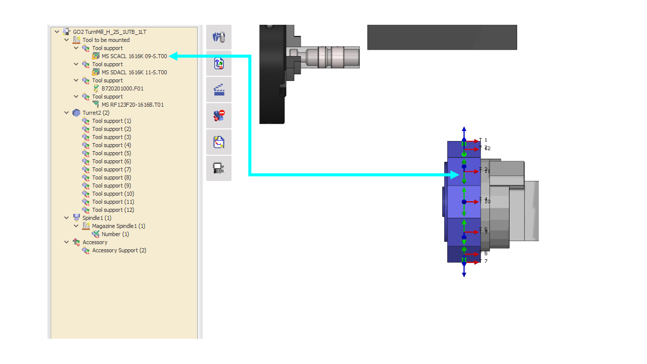
Tooling tree: The tree lists all the tool mounting axes on the machine. It is segregated into the list of tools to be mounted and the racks/turrets/spindles on which the tools can be mounted. |
|
|
|
Graphics window: The 3D model of the machine and its components and tool mounting axes that can be interacted with and manually mount tools and toolholders. This provides a visual understanding of the settings. |
|
|
|
Pop-up menus: Various pop-up menus are available with different functions for each sections, such as the tree, tool/toolholder, machine window, etc. |
|
|
|
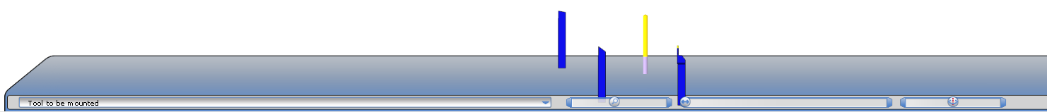
Tool rack: The 3D models of the list of tools to be mounted or already mounted are shown on the rack at the bottom. The user can drag and drop the tools from there to the machine, add toolholders, etc. |
|
|
|
Toolbar Commands: This menu provides advanced settings for the tooling and machining process. |
|
|
Watch a video describing the the interface and their functions. |

|
|
|
General Manipulation The Tooling environment includes useful features, but manipulating complex 3D models (like multi-axis turrets) can be challenging. Users should use filters and mouse controls to improve model positioning and avoid visual obstructions. |

|
|
Manipulation of Tool Rack The Tool Rack is a 3D interactive tool cart used for pre-machining setup. It allows zooming, rotating, and filtering to inspect tools and view only those loaded in the machine magazine. Once tools are mounted, the rack can be minimized as its main use is finished. |

|
|
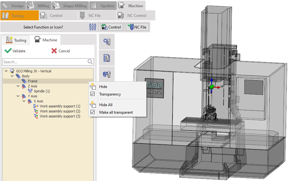
Machine Tree tab In the MTE environment, the Machine Tree tab lets users hide, unhide, or make 3D machine components transparent, unlike the Tooling Tree tab, which is limited to tools and toolholders. It lists all machine components for easy access and allows constrained movement of parts for precise 3D manipulation. |
|
Tool Mounting Methods
There are multiple ways to manually mount tool in MTE:
-
Using the Drag & Drop in the Tooling Tree
|
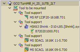
In the tooling menu, you’ll find a section labeled ‘Tool to be Mounted’. Each tool support in this section contains a tool that needs to be mounted. To manually mount a tool, simply drag and drop it from the ‘Tool to be Mounted’ section to an available tool support on your turret or spindle. Example:
|
|
|
|
-
Drag & Drop of 3D tool from Rack to Turret/Spindle
|
In the MTE Tooling Interface, you’ll find a rack at the bottom(shown in Image 3) containing tools ready for mounting. To manually mount a tool, simply drag and drop the 3D model onto the desired turret or spindle tool support, each of which is labeled with a numbered axis system for easy identification. |
|
-
Drag & Drop from Tooling Tree to Turret/spindle.
|
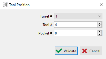
In the "Tool to be mounted" section (shown in Image 1), you can mount tools by dragging them directly to your turret or spindle. The mounting process is simple:
|
|
|
Here you can watch a video demonstrating the different methods of performing manual tool mounting on an MTE machine. |

|
Pop-up menus
Below find the parameters you obtain from the popup menus of each different section:
Machine pop-up
|
|
New |
This option removes all tools currently mounted on the spindle or turret, allowing you to start fresh with a new tool setup. |
||
|
|
Open |
Open existing FMO file |
||
|
|
Save as… |
Save all tool configuration on the machine as an FMO file |
||
|
|
Work-holding device |
|
Work-holding devices/WAGs can be quickly accessed and configured by right-clicking the machine in the tree or the 3D window.
|

|
|
|
Assign tools of machine |
Automatically replace tools defined in the cycles with compatible tools already mounted on the machine(as FMO file). Click on the link for details. |
||
|
|
Tool List |
Open list of tool |
||
|
|
Delete all the toolholders |
Remove all solid toolholders on the machine |
||
|
|
Delete all |
Remove every tool and toolholders mounted on the machine |
||
Tool to be Mounted pop-up
|
|
Display |
To hide/show the tool rack |
|
|
Centre-to-Centre |
To adjust spacing between tools on the tool rack. |
Tool Support pop-up
|
|
Insert |
Allow you to add a solid or standard toolholder |
|
|
|
Hide |
Hide/Unhide the tool and toolholder attached in the selected tool support in the 3D environment |
|
|
|
Transparency |
Make selected component transparent in the 3D environment |
|
|
|
Hide all |
Hide selected group of component in the 3D environment |
|
|
|
Make all transparent |
Make selected group of component in the 3D environment transparent |
|
|
|
Change position |
Allow to move the components of the current tool support to another tool mounting position in the machine. This can be to another turret or rack, another tool support position on the turret or even another pocket position in the same tool support if available. |
|
|
|
Cut |
Removes the components from the selected tool support(maintained in the clipboard) that can be pasted to another tool support position. |
|
|
|
Copy |
Creates a duplicate of the selected tool on the clipboard |
|
|
|
Paste |
Inserts the tool from the clipboard |
|
Tool pop-up
|
|
Automatic Mounting on |
… The turrets and / or racks of machine. For the chosen tool, the user chooses the turret or the rack where to mount it, this is a kind of semi automatic mounting. |
|
|
|
Breaking out the toolholder |
Explode standard toolholders and its tool to be able to replace the toolholder |
|
|
|
Indexing the turret |
For non-coaxial turrets, manually assign tool post positions. |
|
|
|
Settings |
Tools can be adjusted by modifying their effective length (adjustable value), translating them, or rotating them. During adjustment, the tool gauge values—Effective Length, X/Y/Z Translation, and Y/Z Rotation—are dynamically calculated and displayed. |
|
|
|
Group Settings |
It enables collective configuration of tool parameters, such as for tools on a rack in Swiss-type machining. |

|
|
|
Invert Tool Direction |
Rotate the tool 180°. |
|
|
|
Optimum Setting |
Only in milling, it automatically change to the correct useful length. |
|
|
|
Information |
Allows obtaining the tool's characteristics, including the list of cycles using this tool. |
|
|
This video demonstrates how to access and use tool settings in GO2cam’s Tooling Menu via right-click pop-ups. Learn how to invert, lock, or adjust tools and holders for precise setup and real-time adjustments. Watch the video to see these features in action. 
|