
|
|
Identify machining cycles that use intersecting axes. Lock specific axes (spindle or turret) to a desired position, forcing the program to utilize the remaining axis. |
|
In CNC programming, particularly when working with machines that have more than five controllable axes, it's often necessary to fix certain axes in place to simplify motion control, reduce programming complexity, or resolve conflicts between overlapping axis functions. GO2cam provides built-in tools to easily lock specific machine axes—rotational or translational—so that only the necessary degrees of freedom are used during machining operations. Locking unused or redundant axes is essential to ensure stable tool orientation, avoid ambiguous movements, and achieve consistent results in multi-axis setups. Multi-Axis Machines and Concurrent Axes
Modern CNC machines may include additional axes beyond the traditional 5-axis setup. These could be:
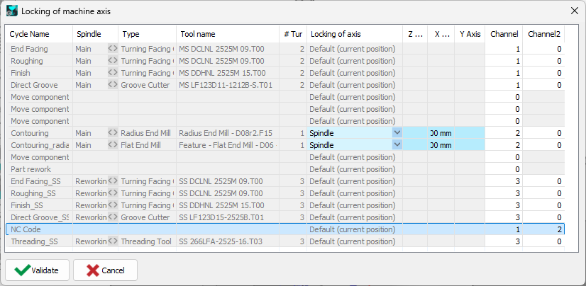
In such cases, multiple axes might be able to achieve the same result. To ensure controlled and predictable tool movement, one of the overlapping axes must be locked, while the other is used by the program. GO2cam performs a full kinematic analysis of the machine configuration—including machine structure, head kinematics, and setup (fixture)—to identify all programmable axes. It then presents a table of axes that are eligible for locking. |
|
|
Techno Functions:
|
|
Using the Axis Locking Feature in GO2cam
|
How to Lock Axes:
Only axes with valid identifiers and programmable status can be locked. |
|
Managing Redundant or Concurrent Axes
Some machines have concurrent axis groups, meaning multiple axes can influence the same tool orientation. For example, both the turret and spindle might provide rotation around a common axis. In these cases:
This prevents duplication of motion commands and ensures smooth, collision-free tool movement. |
|
When to Use Axis Locking
|
Use axis locking in GO2cam when:
|