
Presentation

|
Limitation profiles set space limits for machining. A limitation profile is always closed and defined by 2D geometry. |
The main advantages:
-
avoid designing wireframe geometry,
-
the profiles are used only for the current cycle, then they are hidden automatically,
-
the limitation can be edited and modified afterward to adjust it according to the generated toolpath.
Creation of Automatic Limitation
Several automatic 2D shapes and mode of selection are available on launching the function: Bottom face, Silhouette, Profile, Lateral faces, Edges path, Wireframe, Manual, Ellipse, Rectangle
|
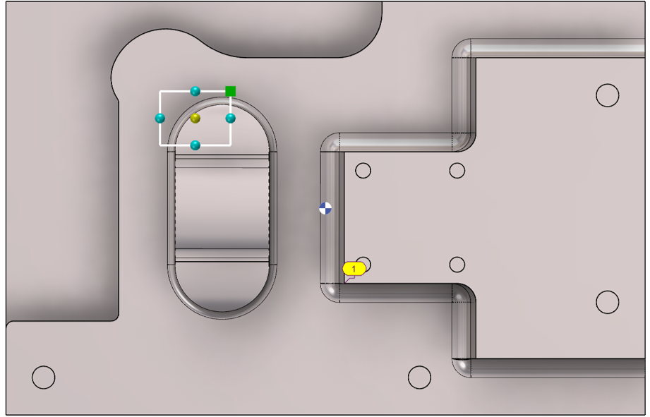
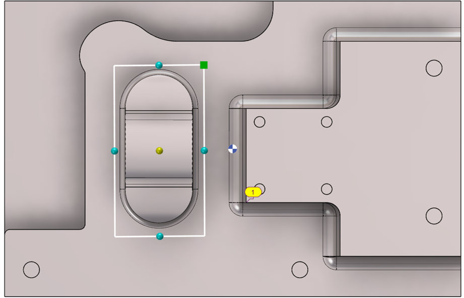
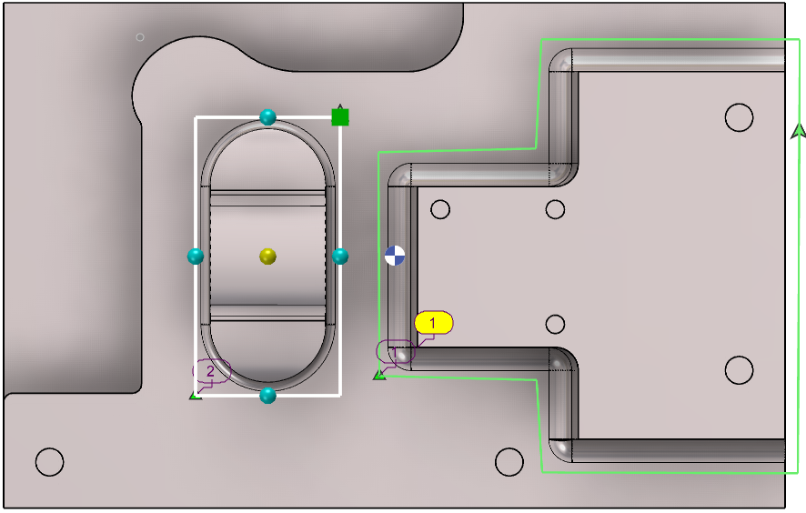
Click on the icon; Create/Edit a profile for limitation to launch the function Select the type of shape definition from the ribbon: Ellipse (or circle), rectangle or manual, etc. Click on the part to position the limitation area: once positioned, the profile can be modified.
|
|
|
|
Rules for adjustment:
|
|
|
|
During the creation of area, several icons are available: Ability to undo the action and go back to previous step [1] Cancel the current area [2] Validate the current area [3] |
|
|
|
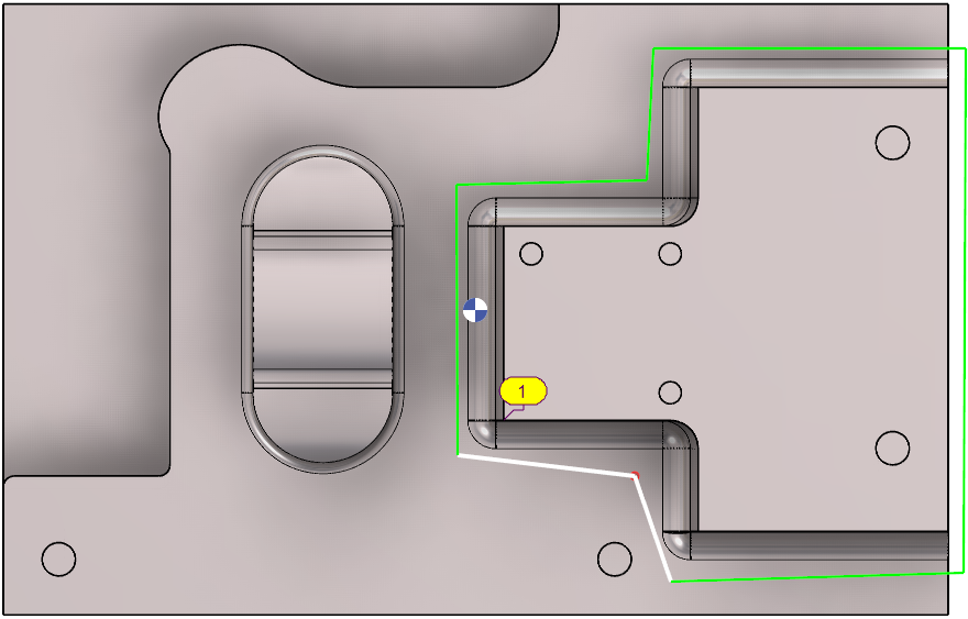
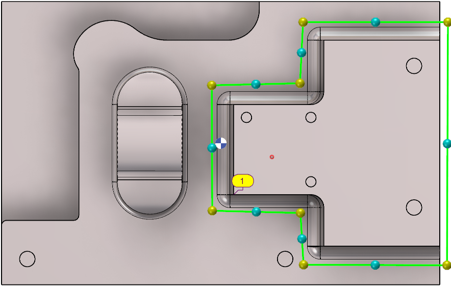
Process for manual creation: The area must be created manually by clicking points on-the-fly. Alternatively, the grid can be invoked (using the CTRL key) to select edges of solids or geometry. After validating the manual shape, numerous adjustments can be made with the colored points as described above: |
||
|
|
|
|
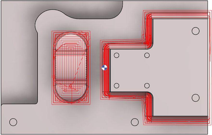
Multiple areas can be created for the same machining selection. Computation is carried out on the defined zones. |
||
|
|
|
|
Watch a video about Automatic Limitation Area on the right. |
|
|