
Definition
To store tools and toolholders with specific characteristics (length corrector, diameter, useful length, etc.), we can create Tooling files (.FMO).
Those files allow for multiple tools and toolholder setups to be saved for later use on the machine. Also, a FMO file is independant from the machine and can be used for several machines.
Create FMO files
There are 3 Methods to save the tooling configuration into FMO files.
Without a Part:
-
Load a machine file including a 3D model file (.mcb)
-
In MTE Tooling menu, insert some tools and/or toolholders on the Tools Supports
-
Confirm → the FMO file is saved in the Kinemac folder.
Without a Part but with fixed or prepared tools in the machine file:
-
Load this machine file including a 3D model file (.mcb)
-
In MTE Tooling menu, click Auto Mounting,
-
Confirm → the FMO file is saved in the Kinemac folder.
With a Machined Part:
|
|
|
Use FMO Files
|
|
|
|
|
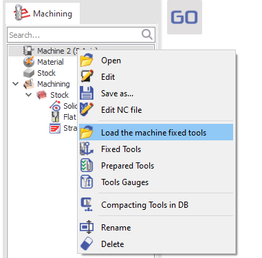
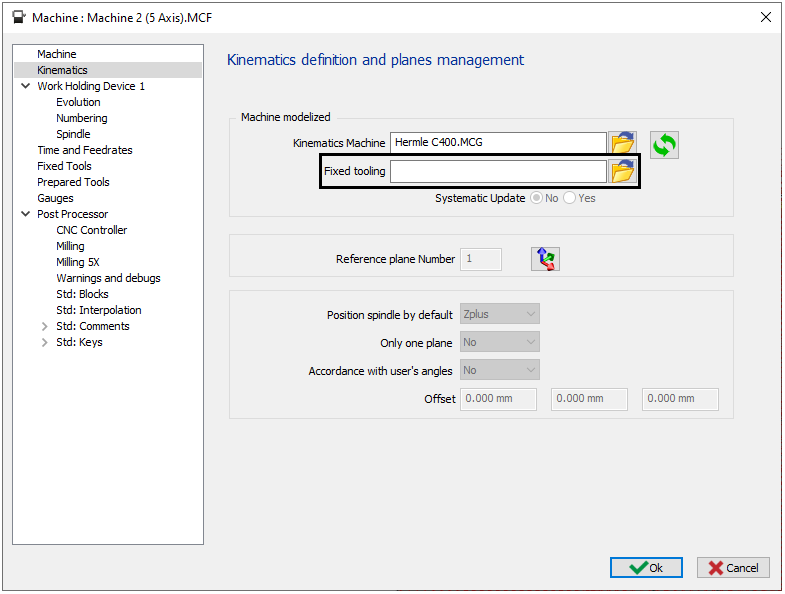
Option Systematic Update in the Machine file:
|
|
|
▶️ This video shows the creation and the definition of FMO file in the machine file. |

|
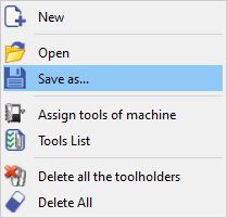
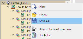
Assign Tools of the Machine
|
|
This command is designed to simplify the transition from programming to production by automatically replacing generic or placeholder cycle tools with the actual tools mounted on the machine. |
|
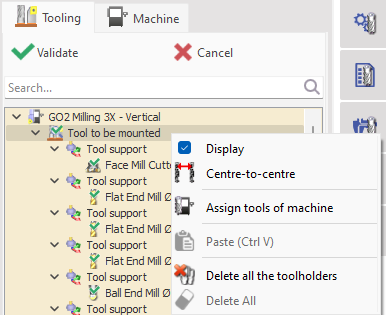
The Assign Tools of Machine command can be accessed by right-clicking on the machine or the Tool to be mounted section. When selected, a dialog window appears displaying the placeholder tools along with the compatible mounted tools. Incompatible tools are highlighted for easy identification. Validate the selection to replace and mount the tools. 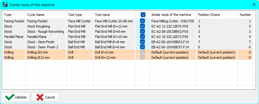
|
|
|
This feature is particularly useful in workshops with multiple similar machines, where each machine may have its own mounted toolset, possibly from different manufacturers. During programming, machining cycles can be defined using any compatible tools to validate the operations and toolpaths. Once the target machine is selected, this command quickly substitutes the programmed tools with the actual mounted tools from the FMO file. After the replacement, the mounting process can be finalized as usual. Watch a video demonstrating the the functioning of the command on the right. |

|