
The selection of geometry to program operations is a complex topic.
Almost each machining menu has his own method and characteristics. It also depends on the type of geometry, wireframe or solid.
Many information can be found here:
Direction Of Profiles and Toolpaths
In general:
-
For milling, the G17 ( Z+ Plane) is the default setting. It defines the working plane where the X and Y axes determine the toolpath. Imagine a flat surface where the machine moves the cutting tool across the length (X) and width (Y).
-
For turning the G18 (Y+ Plane) is the default setting. Here, the toolpath is defined by the X and Z axes. In simpler terms, the tool moves along the length (X) and depth (Z) of the material.
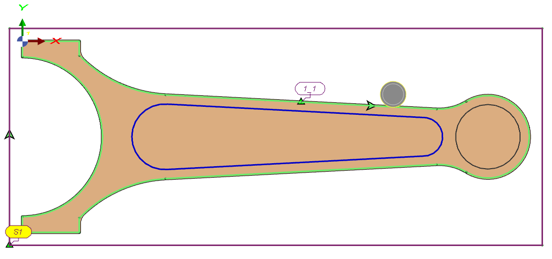
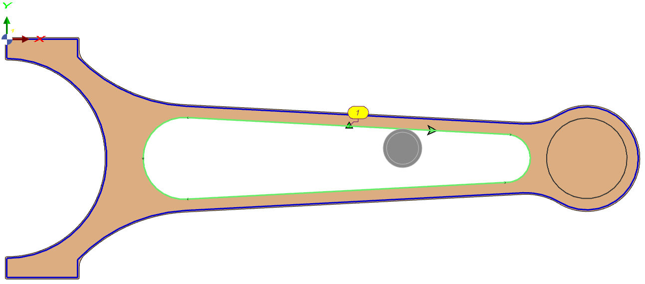
The direction of the profile selected determines the position of the toolpath (Right/Left). See an example on a milling part below:
|
|
Selection of Hidden Faces
|
Use hidden-face selection to choose geometry that is not directly visible in the current view. This applies to any concealed surfaces (e.g., mirrored, occluded, or rear-facing faces). Workflow: Hold Shift, and click the intended face. A context list shows faces under the cursor by priority; hover to preview outlines. Select the correct face to include it in the machining selection—no view rotation required. This selection workflow is also applicable in the design environment. |

|