
|
|
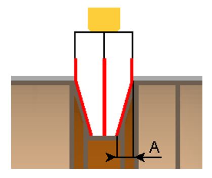
This cycle is exclusively used for ‘O-ring or circlips’ toolpath, with specific constraints regarding the groove shape. |
Key Points
|
To be able to apply the O’ring toolpath, the groove must be defined in a very specific way:
If these conditions are not respected, GO2cam displays an error message and the cycle is set in ‘Waiting’ status in the machining tree. |
|
Strategy Parameters
|
Dialog Area |
Parameters |
|
|
Toolpath |
||
|
|
||
|
Machining Strategy |
Z step |
|
|
XY Stock allowance |
||
|
Z Stock allowance |
||
Movement Parameters
|
Dialog Area |
Parameters |
|
|
Approach and Return Characteristics |
||
|
Finish overlength |
|
|
Technology Parameters
|
Dialog Area |
Parameters |
|
|
Cutting Conditions |
Quality |
Cutting Speed |
|
Spindle speed |
Speed range |
|
|
Feedrate in Z |
Feedrate |
|
|
Feedrate in X |
Spindle direction |
|
|
Maxi spindle speed |
||
|
|
||
|
Tool number |
Specific Number |
|
|
Radius compensation number |
Length compens. nb 1 |
|
|
Length compens. nb 2 |
|
|
|
Users Fields |
Comment |
Control Device |
|
Machining Set |
|
|
Options Parameters
|
Dialog Area |
Parameters |
|
|
Management of collisions |
||
|
Safety distance in Z for rapids |
Safety distance in X for rapids |
|
|
Curves Computing |
Curve Tolerance |
Curve explode into |
|
Stock to keep |
|
|