
|
|
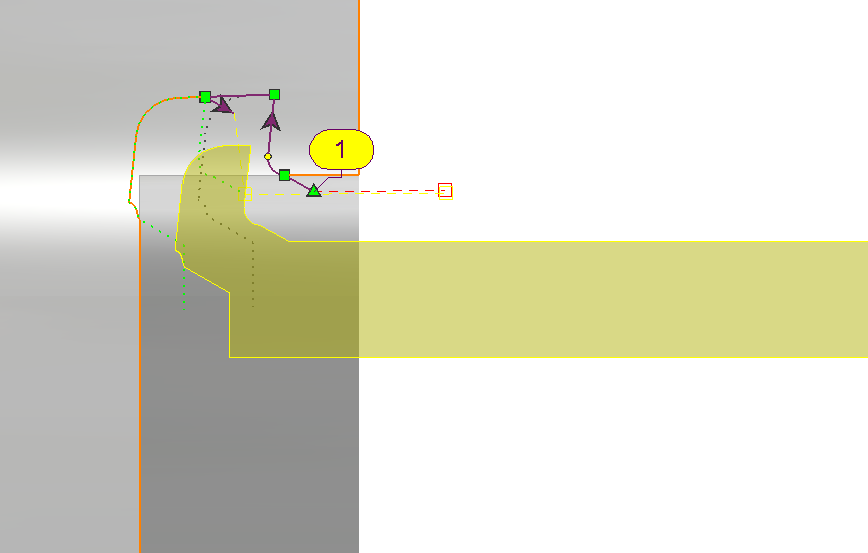
This is a very specific toolpath since it follows any geometry with standard turning tool and specific forming tools. One pass is calculated, but be very careful: there is no gouge checking on this cycle! Also, there is no removal material on the stock! |
Key Points
|
The toolpath is determined manually, just following the selected geometry with G01 and G02/03 motions. The approach and return points are set in the geometry selection. These points control where the cutting tool starts and ends its movement relative to the workpiece.
|
|
|
|
|
The stock is now computed for a point to point operation. |
|
|
▶️ Watch a video showing and example of the application of this cycle: 
|
Strategy Parameters
|
Dialog Area |
Parameters |
|
|
Toolpath |
Cycle type |
|
|
|
||
Movement Parameters
|
Dialog Area |
Parameters |
|
|
Approach and Return Characteristics |
Safety distance |
|
Technology Parameters
|
Dialog Area |
Parameters |
|
|
Cutting Conditions |
Quality |
Cutting Speed |
|
Spindle speed |
Speed range |
|
|
Feedrate in Z |
Feedrate |
|
|
Feedrate in X |
Spindle direction |
|
|
Maxi spindle speed |
||
|
|
||
|
Tool number |
Specific Number |
|
|
Radius compensation number |
Length compens. nb |
|
|
User information |
Comment |
Control Device |
|
Machining Set |
|
|
Options Parameters
|
Dialog Area |
Parameters |
|
|
Management of collisions |
||
|
Curves Computing |
Curve Tolerance |
Curve explode into |