
|
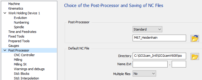
The standard has three configuration pages to manage all options available: The first page “CNC Controller” is about CNC options. The second page “Milling” allows to adapt the output for Milling, tools, coolant and origins. The third page “Milling” is about 5 axis parameters. |
|
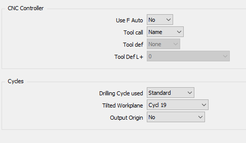
CNC Controller page
CNC Controller Section
|
Use F Auto
|
Option |
Result |
|
No |
… TOOL CALL 1 Z S1200 … L X0 Y0 FMAX L Z20 F200 … |
|
Yes |
… TOOL CALL 1 Z S1200 F200 … L X0 Y0 FMAX L Z20 FAUTO … |
Tool Call
|
Option |
Result |
|
Number |
… TOOL CALL 1 Z S1200 … |
|
Name |
… TOOL CALL “MILL_D10” Z S1200 … |
Tool Def
|
Option |
Result |
|
None |
BEGIN PGM 1 MM … TOOL CALL 1 Z S1500 … TOOL CALL 2 Z S2000 … END PGM 1 |
|
Start |
BEGIN PGM 1 MM TOOL DEF 1 L+80 R+6 TOOL DEF 2 L+80 R+10 … TOOL CALL 1 Z S1500 … TOOL CALL 2 Z S2000 … END PGM 1 |
|
Tool |
BEGIN PGM 1 MM … TOOL DEF 1 L+80 R+6 TOOL CALL 1 Z S1500 … TOOL DEF 2 L+80 R+10 TOOL CALL 2 Z S2000 … END PGM 1 |
Cycles Section
Drilling Cycle used
|
Option |
Result |
|
Standard |
… L X-20. Y+20. M03 FMAX L Z+50. FMAX Z+2. CYCL DEF 1.0 PECKING CYCL DEF 1.1 SET UP +2 CYCL DEF 1.2 DEPTH -10.412 CYCL DEF 1.3 PECKG +10.412 CYCL DEF 1.4 DWELL +0 CYCL DEF 1.5 F606 CYCL CALL … |
|
Universal |
… L X-20. Y+20. M03 FMAX L Z+50. FMAX CYCL DEF 200 DRILLING~ Q200=2 ;SET-UP CLEARANCE~ Q201=-10.412 ;DEPTH~ Q206=606.4 ;FEED RATE FOR PLNGNG~ Q202=10.412 ;PLUNGING DEPTH~ Q210=0 ;DWELL TIME AT TOP~ Q203=0 ;SURFACE COORDINATE~ Q204=2 ;2ND SET-UP CLEARANCE~ Q211=0 ;DWELL TIME AT DEPTH~ Q395=0 ;DEPTH REFERENCE CYCL CALL … |
Tilted Workplane
|
Option |
Result |
|
Cycl Def 19 |
… CYCL DEF 19.0 WORKING PLANE CYCL DEF 19.1 A-90. B+0. C+90. L A+Q120 C+Q122 R0 FMAX … |
|
Plane Spatial |
… PLANE SPATIAL SPA-90 SPB+0 SPC+90 TURN MB MAX FMAX SEQ- TABLE ROT … |
Output Origin Workplane
|
Option |
Result |
|
No |
… TOOL CALL 1 Z S1500 … |
|
Cycl Def 7 |
… TOOL CALL 1 Z S1500 CYCL DEF 7.0 DATUM SHIFT CYCL DEF 7.1 #1 … |
|
Cycl Def 247 |
… TOOL CALL 1 Z S1500 CYCL DEF 247 DATUM SETTING~ Q339=1 ;DATUM NUMBER … |
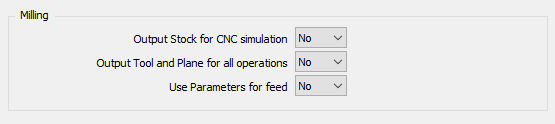
Milling page
Milling Section
|
Output Stock for CNC Simulation
|
Option |
Result |
|
No |
BEGIN PGM 1 MM … |
|
Yes |
BEGIN PGM 1 MM BLK FORM 0.1 Z X-42.5 Y-35 Z-39 BLK FORM 0.2 X+42.5 Y+39 Z+1 … |
Output Tool and Plane for all operations
|
Option |
Result |
|
No |
… ;OP 1 WITH TOOL 1 AND PLANE 1 TOOL CALL 1 Z S1500 PLANE SPATIAL SPA-90 SPB+0 SPC+90 TURN MB MAX FMAX SEQ- TABLE ROT … ;OP 2 WITH TOOL 1 AND PLANE 1 … |
|
Yes |
… ;OP 1 WITH TOOL 1 AND PLANE 1 TOOL CALL 1 Z S1500 PLANE SPATIAL SPA-90 SPB+0 SPC+90 TURN MB MAX FMAX SEQ- TABLE ROT … ;OP 2 WITH TOOL 1 AND PLANE 1 TOOL CALL 1 Z S1500 PLANE SPATIAL SPA-90 SPB+0 SPC+90 TURN MB MAX FMAX SEQ- TABLE ROT … |
Use Parameters for Feed
|
Option |
Result |
|
No |
T1 M6 G0 X.. Y.. G43 H1 Z.. Z-.. F160 G1 X.. Y.. F200 … |
|
Yes |
FN 0: Q1 = 200 FN 0: Q2 = 150 T1 M6 G0 X.. Y.. G43 H1 Z.. Z-.. FQ2 G1 X.. Y.. FQ1 … |
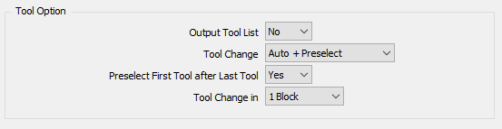
Tool Option Section
|
Output Tool List
|
Option |
Result |
|
No |
BEGIN PGM 1 MM … |
|
Yes |
BEGIN PGM 1 MM ;START TOOL LIST ;T1 END MILL D10 ;T2 DRILL D8 ;… ;END TOOL LIST … |
Tool Change
|
Option |
Result |
|
Manual |
… ;END MILL D10 M0 … |
|
Automatic |
… ;END MILL D10 TOOL CALL 1 Z S1500 … |
|
Auto + Preselect |
… ;END MILL D10 TOOL CALL 1 Z S1500 TOOL DEF 2 … |
Preselect First Tool after Last Tool
|
Option |
Result |
|
No |
;FIRST OPERATION TOOL CALL 1 Z S1500 TOOL DEF 2 … … ;LAST OPERATION TOOL CALL 5 Z S1250 … M30 |
|
Yes |
;FIRST OPERATION TOOL CALL 1 Z S1500 TOOL DEF 2 … … ;LAST OPERATION TOOL CALL 5 Z S1250 TOOL DEF 1 … M30 |
Tool Change in
This option has no influence on the output.
|
Option |
Result |
|
1 Block |
… TOOL CALL 1 Z S1500 … |
|
2 Blocks |
… TOOL CALL 1 Z S1500 … |
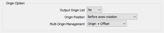
Origin Option Section
|
Output Origin List
|
Option |
Result |
|
No |
BEGIN PGM 1 MM … |
|
Yes |
BEGIN PGM 1 MM ;START ORIGIN LIST ;1 ;2 ;END ORIGIN LIST … |
Origin Position
|
Option |
Result |
|
After Axes Rotation
|
… TOOL CALL 1 Z S1500 A90 C90 CYCL DEF 247 DATUM SETTING~ Q339=1 ;DATUM NUMBER … |
|
Before Axes Rotation |
… TOOL CALL 1 Z S1500 CYCL DEF 247 DATUM SETTING~ Q339=1 ;DATUM NUMBER A90 C90 … |
Multi Origin Management
|
Option |
Result |
|
Origin Only |
… CYCL DEF 247 DATUM SETTING~ Q339=1 ;DATUM NUMBER … |
|
Origin + Offset |
… CYCL DEF 247 DATUM SETTING~ Q339=1 ;DATUM NUMBER CYCL DEF 7.0 DATUM SHIFT CYCL DEF 7.1 X-50. CYCL DEF 7.2 Y-25. CYCL DEF 7.3 Z-50. … |
Without MTE :
If the option is set to “Origin Only” for each origin define on the part, we will output a different G code, G54, then G55, G56 … It means you are limited by the number of origin managed by the CNC. If you can have more origin, you must use the second option “Origin + Offset”
If the option is set to “Origin + Offset” it will only output Datum and offset with Cycl def 7.
With MTE :
The origin can be defined in the name of the origin with the following syntax “$1_”. It means Datum 1 will be used in the NC program. If there is no decoded name defined, it will output the default datum 1.
If you use “Origin + Offset”, you must use only one origin for all your operation because all the offset are computed from the reference plane origin or single origin.
You can add any text after the underscore to recognized your offset “$1_Up”, “$1_Right”, …
With 5 axis machine:
The origin offset is output in the same time of the tilted plane function.
Coolant Option Section

|
Coolant Activation Position
We will have the same result using ”with Spindle” and “with plunge move”.
M13 will be used to output the coolant and the spindle in the same time.
|
Option |
Result |
|
With Spindle |
… TOOL CALL 1 Z S1500 L X.. Y.. M13 FMAX L Z.. FMAX … |
|
With Plane Move |
… TOOL CALL 1 Z S1500 L X.. Y.. M13 FMAX L Z.. FMAX … |
|
With Plunge Move |
… TOOL CALL 1 Z S1500 L X.. Y.. M03 FMAX L Z.. M08 FMAX … |
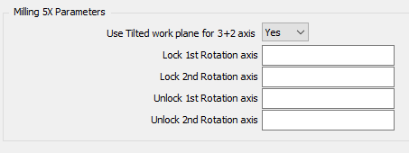
Milling 5X page
Milling 5X Parameters
|
Use Tilted work Plane for 3+2 Axis
|
Option |
Result |
|
No |
… TOOL CALL 1 Z S1500 C180 A-90 … |
|
Yes |
… TOOL CALL 1 Z S1500 PLANE SPATIAL SPA-90 SPB+0 SPC+180 TURN MB MAX FMAX SEQ- TABLE ROT … |
Rotation Axis
|
Option |
Result |
Option |
Result |
|
Lock 1st Rotation Axis |
Lock 2nd Rotation Axis |
||
|
empty |
… C180 … |
empty |
… B-90 … |
|
“M10” |
… C180 M10 … |
“M12” |
… B-90 M12 … |
|
Unlock 1st Rotation Axis |
Unlock 2nd Rotation Axis |
||
|
empty |
… C180 … |
empty |
… B-90 … |
|
“M11” |
… M11 C180 … |
“M13” |
… M13 B-90 … |
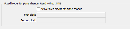
Fixed blocks for plane change (Used without MTE)
|
Active fixed blocks for plane change
This option is used only if there is no kinemac defined in the machine configuration.
|
Option |
Result |
|
check |
The fixed blocks defined will be output if there is a plane change |
|
uncheck |
The standard blocks will be output if there is a plane change. G0 G91 G28 Z0 |
First and Second Block
To avoid the standard output, check the option to activate the fixed blocks and keep the first and second block fields empty.
|
Option |
Result |
|
Empty |
… … |
|
“G0 Z100” |
… L Z100 FMAX … |
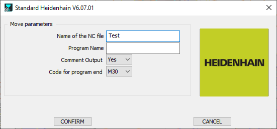
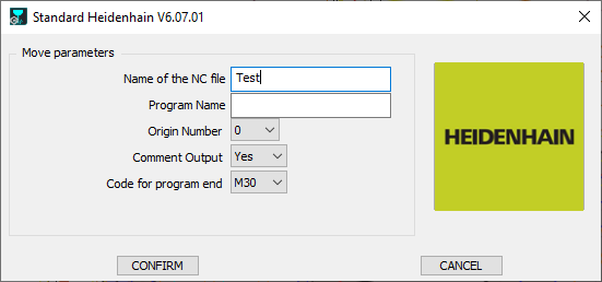
Launch page
|
With machine kinematic defined |
Without machine kinematic defined |
|
|
Name of the NC File
Define here the Name of the generated NC file. The extension must to be defined in the MCF configuration.
Program Number
If nothing is defined, the program Name will be set to 1.
|
Option |
Result |
|
“empty” |
BEGIN PGM 1 MM … … END PGM 1 MM |
|
“PROG” |
BEGIN PGM PROG MM … … END PGM PROG MM |
Comment Output
|
Option |
Result |
|
No |
… TOOL CALL 1 Z S1500 … |
|
Yes |
… ;FACING ;END MILL D12 T1 M6 … |
Origin Number
This parameter is used only if kinematic is not defined in the machine file. The parameter defines the first origin used in the NC program.
If the parameter to treat multi origin is set on “Origin Only” the origin number is incremented when a plane changes.
|
Option |
Result Until 8055 |
|
0 |
13 TOOL CALL 1 Z S1273 14 CYCL DEF 247 DATUM SETTING~ Q339=0 ;DATUM NUMBER… |
|
1 |
13 TOOL CALL 1 Z S1273 14 CYCL DEF 247 DATUM SETTING~ Q339=1 ;DATUM NUMBER |
Code for Program End
|
Option |
Result |
|
M30 |
… … M30 END PGM 1 MM |
|
M02 |
… … M02 END PGM 1 MM |
Specific Information
How to output Cycl Def 202?
|
This cycle is used to do a ream with a single edge bore tool. For more information about this cycle see the heidenhain manual. |
CYCL DEF 202 BORING~ Q200=2 ;SET-UP CLEARANCE~ Q201=-50 ;DEPTH~ Q206=79.6 ;FEED RATE FOR PLNGNG~ Q211=0 ;DWELL TIME AT DEPTH~ Q208=500 ;RETRACTION FEED RATE~ Q203=0 ;SURFACE COORDINATE~ Q204=2 ;2ND SET-UP CLEARANCE~ Q214=2 ;DISENGAGING DIRECTN~ Q336=90 ;ANGLE OF SPINDLE |
|
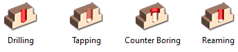
Operation to define : Reaming |
|
|
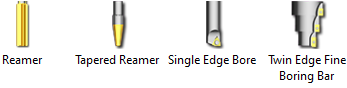
Tool to choose : Single Edge Bore |
|
|
Parameter |
Set |
|
Q214=2 ;DISENGAGING DIRECTN |
Is compute regarding the index angle. 0 for 0 degrees 1 for 90 degrees 2 for 180 degrees 3 for 270 degrees |
|
Q336=90 ;ANGLE OF SPINDLE |
If Index Angle is different of 0, 90, 180 or 270, it is forced to 0 |
How to output Cycl Def 208?
|
This cylce is used to machine a hole with helix interpolation. For more information about this cycle see the heidenhain manual. |
CYCL DEF 208 BORE MILLING~ Q200=2 ;SET-UP CLEARANCE~ Q201=-50 ;DEPTH~ Q206=1018.4 ;FEED RATE FOR PLNGNG~ Q334=5 ;PLUNGING DEPTH~ Q203=0 ;SURFACE COORDINATE~ Q204=2 ;2ND SET-UP CLEARANCE~ Q335=20 ;NOMINAL DIAMETER~ Q342=0 ;ROUGHING DIAMETER~ Q351=1 ;CLIMB OR UP-CUT |
|
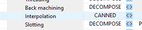
To be used, the gpp configuration must be set in canned for “Interpolation” The option for Drilling cycle used has to be set on “Universal” |
|
|
Operation to define : “Interpolation” |
|
|
The operation has to be define with the following parameters. If one is different the toolpath will be decomposed. |
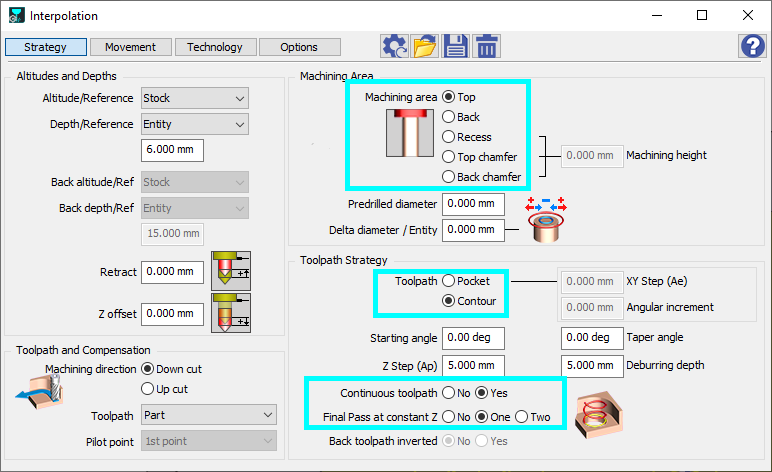
|