
Presentation
The Machine File is the association of a post-processor and parameters regarding the machine. Even if you have one only post-processor, you can create several machine files, one for each machine of your machine shop.
However, defining a machine file is not obligatory to generate the ISO codes.
Creating/Loading a Machine File
To create/load an existing machine file, do a right-click on the Machine line of the Machining Tree:
|
Open |
Load a machine file via the Windows explorer (Mac folder) |

|
|
Edit |
Open the machine file to create or modify a machine |
|
|
Save as... |
Register the machine with all the adjustments done |
|
|
Edit NC file |
Open an NC file already computed (Iso folder) |
|
|
Fixed Tools / Prepared Tools / Tools Gauges (only Milling and Turning) |
Open the machine file directly in a specific tab. If fixed tools have been defined, they are displayed in the machining tree and you can drag and drop them to copy them in a cycle. |
|
|
Compacting Tools in DB |
|
|
|
Rename |
Rename a machine file, and If you do ‘Save as…’, and if there are some files linked with the same name, then those files will also be copied under the new given name (image, XML ...). |
|
|
Delete |
Cancel the machine chosen |
Creation of Machine File
|
▶️ Watch a video about the Creating/Loading a Machine File. 

|
Edit
The machine file is different if you create a milling center, a lathe center or an EDM machine.
The example chosen is the milling page. The way to use it is the same for the three technologies:
-
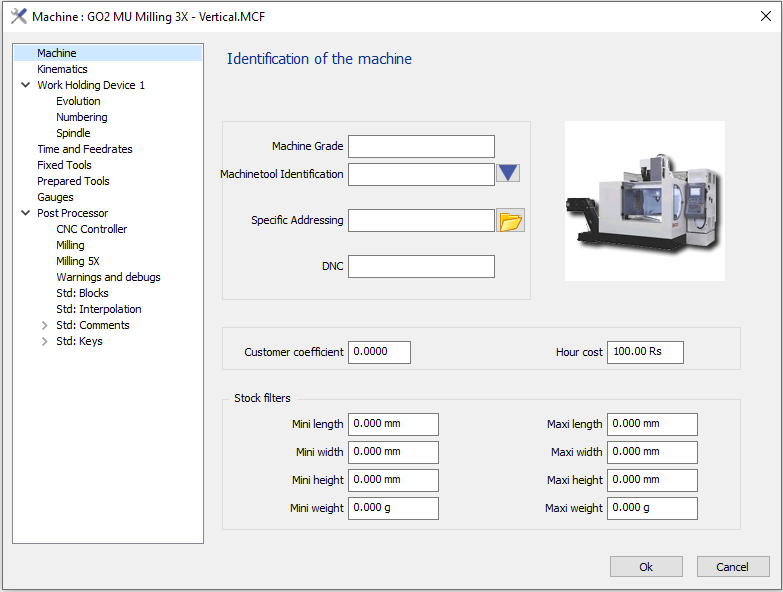
Choose the Post-processor in the standard folder (or specific), click the folder button and choose the post-processor in the Windows explorer
-
Define some specific parameters in the several pages.
-
For e.g. in the Kinematics page, you can choose a Kinematics Machine .MCG file.
You will still be able to create your machine file even if you do not have the .MCG machine file. However you cannot simulate in the MTE environment.

|
Downloading and Loading Machine Kinematics via Unique ID This feature simplifies how you receive and set up machine configurations by eliminating the need for manual file transfers. Instead of handling attachments, you can now use a unique ID provided by your VAR to sync data directly into your software. How to Load Your Machine To get started, ensure you have received the specific ID number from your VAR.
|
|
▶️ This video demonstrates both downloading and uploading machine files; however, only the download process is relevant for clients. 
|
|

You can create several machines the same way. Now you can load the machine you need when opening GO2cam, but you can also define a default machine in Tools \ Options \ Machining . |
|
|
▶️ Watch a video about Specific Addressing below. 
|
Main Spindle / Reworking Spindle (Turning)
Those 2 pages are dedicated to the definition of spindles characteristics.
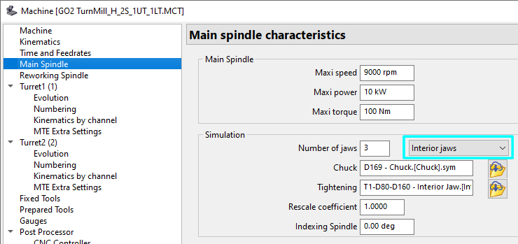
Especially, this is the dialogue where you can choose the system of clamping used for simulation; you can declare the symbol files used for chuck, jaws and collets representation.
Click here to get more information avout the creation of the symbols: https://go2cam.scrollhelp.site/en/go2cam/help/creation-of-components
|
Special case of internal jaws In the Machine settings, it is mandatory to change the jaw option to interior jaws for the machine to adjust itself. |
|
|
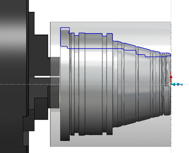
Then, it is important to understand that Interior jaws are created using the same procedure as exterior jaws. There is no specific rule for creating the system of axes for an interior jaw. The directions of the axes remain the same. The important point is the position of the system of axes, which determines the clamping position. For internal tightening, the Z axis of the tightening system of axes must be oriented in the same direction as the X axis of the chuck system of axes. Multiple tightening positions can be defined on the same jaw. To define several positions, create an additional system of axes for each required clamping position. For example, two tightening positions can be defined on the same interior jaw by creating two corresponding systems of axes. |
|
Management of Tools
With a direct access in the machining tree, it is possible define fixed and prepared tools and define their length gauges. You can also change the numbering of tools in the machine file. In doing so, this will allow the user to see the modified numbers in the Tools Library.
There are two videos below demonstrating the direct access to tools and also the numbering of tools.
|
▶️ Watch a video on Tools in Machine File 
|
▶️ Watch a video on Numbering of tools 
|