
General Information
|
The standard has four configuration pages to manage all options available :
|
|
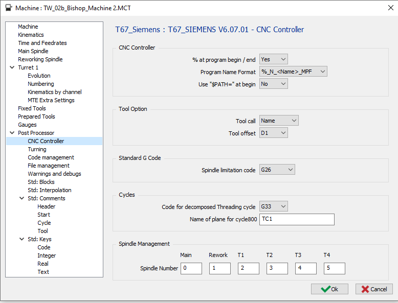
1 CNC Controller Page
|
1.1 CNC Controller - % at program begin / end
|
Option |
Result |
|
No |
N5 G00 G53 Z0 … … M30 |
|
Yes |
% N5 G00 G53 Z0 … … M30 % |
1.2 CNC Controller - Program name format
Even if the % at program begin / end is deactivated in the option before, the 2 first options for the program name will output %
|
Option |
Result |
|
%_N_<name>_MPF |
%_N_PROG_MPF N5 G00 G53 Z0 … … |
|
%MPF<number> |
%MPF1 N5 G00 G53 Z0 … … |
|
without |
G00 G53 Z0 … … |
1.3 CNC Controller – Use “$PATH=” at Begin
The option is available only if the Program Name Format is set to “%_N_<name>_MPF”.
|
Option |
Result |
|
No |
%_N_PROG_MPF N5 G00 G53 Z0 … … |
|
Yes |
%_N_PROG_MPF ;$PATH=/_N_MPF_DIR N5 G00 G53 Z0 … … |
1.4 Tool Option – Tool Call
|
Option |
Result |
|
Number |
… … T01 M06 … … |
|
Name |
… … T=”CNMG 04” M06 … … (CHIPBREAKING CYCLE) G83 Z-6 Q2000 F500 G80 … … |
1.5 Tool Option – Tool Offset
|
Option |
Result |
|
D1 |
… T01 D01 M06 … … T02 D01 M06 … |
|
D.. |
… T01 D01 M06 … … T02 D02 M06 … |
1.6 Standard G code – Spindle Limitation Code
|
Option |
Result |
|
G26 |
… G26 S2500 … |
|
LIMS |
… LIMS=2500 … |
1.7 Cycles – Code for decomposed Threading Cycle
The Threading cycle has to be set to “decomposed” in the generator.
|
Option |
Result |
|
G33 |
… G01 X39.071 F3.5 G33 Z-43 G00 X44 Z2.5 … |
|
G32 |
… G01 X39.071 F3.5 G32 Z-43 G00 X44 Z2.5 … |
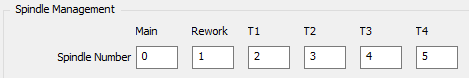
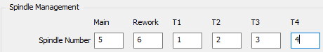
1.8 Spindle Management – Spindle Number
Define here the number that will be used by the SETMS function for :
-
Main : Main Spindle
-
Rework : Rework Spindle
-
T1 : First turret
-
T2 : Second turret
-
T3 : Third turret
-
T4 : Forth turret
If the number is set to 0, SETMS will be output without number.
|
Option |
Result |
|
|
… ;Choose the main spindle SETMS … … ;Choose the rework spindle SETMS(1) … … |
|
… ;Choose the main spindle SETMS(5) … … ;Choose the rework spindle SETMS(6) … … |
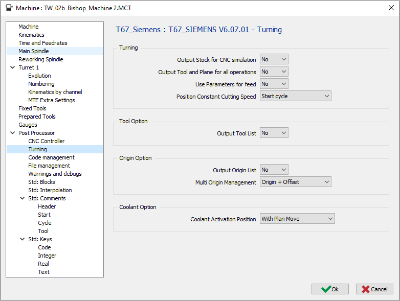
2 Turning page
|
2.1 Turning – Output Stock for CNC Simulation
|
Option |
Result |
|
No |
%_N_PROG_MPF … … |
|
Yes |
%_N_PROG_MPF N5 WORKPIECE(,"",,"CYLINDER",64,2,-32,-80,30) … … |
2.2 Turning – Output Tool and Plane for all operations
|
Option |
Result |
|
No |
… ;OP 1 WITH TOOL 1 AND PLANE 1 T01 D01 M06 CYCLE800(1,"TC1",0,39,0,0,0,90,-90,0,0,0,0,-1) … … ;OP 2 WITH TOOL 1 AND PLANE 1 … |
|
Yes |
… ;OP 1 WITH TOOL 1 AND PLANE 1 T01 D01 M06 CYCLE800(1,"TC1",0,39,0,0,0,90,-90,0,0,0,0,-1) … … ;OP 2 WITH TOOL 1 AND PLANE 1 T01 D01 M06 CYCLE800(1,"TC1",0,39,0,0,0,90,-90,0,0,0,0,-1) … |
2.3 Turning – Use Parameters for Feed
|
Option |
Result |
|
No |
… T01 D01 G00 X20 Z2 G01 Z-20 G95 F0.1 … … |
|
Yes |
R21 = 0.1 … T01 D01 G00 X20 Z2 G01 Z-20 G95 FR21 … … |
2.4 Turning – Position Constant Cutting Speed
|
Option |
Result |
|
Start cycle |
T01 D01 G26 S9000 G96 S40 M04 G00 G90 X24. Z2.8… … |
|
Start machining |
T01 D01 G97 S284 M04 G00 G90 X24. Z2.8 G26 S9000 G96 S40 M04 G01 G95 Z0. F0.1 … |
2.5 Tool Option – Output Tool List
|
Option |
Result |
|
No |
%_N_PROG_MPF … … |
|
Yes |
%_N_PROG_MPF ;START TOOL LIST ;T1 CMNG 04 ;T2 ... ;T2 ... ;END TOOL LIST … … |
2.6 Origin Option – Output Origin List
|
Option |
Result |
|
No |
%_N_PROG_MPF … |
|
Yes |
%_N_PROG_MPF ;START ORIGIN LIST ;G54 ;G55 ;... ;END ORIGIN LIST … |
2.7 Origin Option – Multi Origin Management
|
Option |
Result |
|
Origin Only |
% O1000 … G54 … |
|
Origin + Offset |
% O1000 … G54 TRANS X10 Y20 Z10 … |
Without MTE :
If the option is set to “Origin Only” for each origin define on the part, we will output a different G code, G54, then G55, G56 … It means you are limited by the number of origin managed by the CNC. If you can have more origin, you must use the second option “Origin + Offset”
If the option is set to “Origin + Offset” it will only output G54 and offset with TRANS
With MTE :
The origin can be define in the name of the origin with the following syntax “$G54_”. It means G54 will be used in the NC program. If there is no decoded name define, it will output the default origin G54.
If you use “Origin + Offset”, you must use only one origin for all your operation because all the offset are compute from the reference plane origin or single origin.
You can add every text after the underscore to recognized your offset “$G54_Up”, “$G54_Right”, …
With 5 axis machine :
The origin offset is output with the tilted plane function Cycle800 if is set to be output. So it means no TRANS is output.
2.8 Coolant Option – Coolant Activation Position
The second and third option will give the same output for turning operation.
There will be a difference by milling operations using livetools.
|
Option |
Turning operation |
Milling operation (livetool) |
|
With Spindle |
… T01 D01 M06 S1000 M03 M08 G00 X15 Z2 … … |
… T01 D01 M06 S1000 M03 M08 G00 X15 C0 Z2 … |
|
With Plane Move |
… … T01 D01 M06 S1000 M03 G00 X15 Z2 M08 … … |
… … T01 D01 M06 S1000 M03 G00 X15 C0 M08 Z2 … |
|
With Plunge Move |
… T01 D01 M06 S1000 M03 G00 X15 Z2 M08 … … |
… T01 D01 M06 S1000 M03 G00 X15. C0 Z2 M08 … |
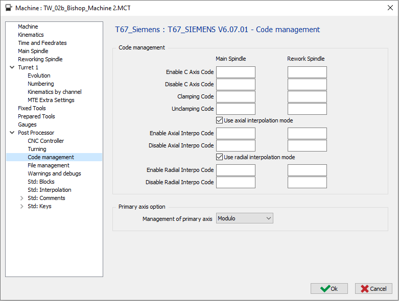
3 Code management page
|
3.1 Code Management – Enable C Axis Code
|
Option |
Result |
|
“empty” |
… T01 D01 M06 S1000 M03 G17 G28 G90 H0 C10 … |
|
M51 |
… T01 D01 M06 S1000 M03 G17 M51 G28 G90 H0 C10 … |
3.2 Code Management – Disable C Axis Code
|
Option |
Result |
|
“empty” |
… X200 M09 … |
|
M50 |
… X200 M50 M09 … |
3.3 Code Management – Clamping Code
|
Option |
Result |
|
“empty” |
… C10 G01 Z-10 … |
|
M10 |
… C10 M10 G01 Z-10 … |
3.4 Code Management – Unclamping Code
|
Option |
Result |
|
“empty” |
… G0 Z20 C10 … |
|
M11 |
… G0 Z20 M11 C10 … |
3.5 Code Management – Use axial interpolation mode
If machine don’t have TRANSMIT option the output can be done in decomposed.
No circular interpolation will be output don’t use tool offset
|
Option |
Result |
|
|
Output axial operation with TRANSMIT |
|
|
Output axial operation decomposed |
3.6 Code Management – Enable Axial Interpo Code
If the field is empty, the code used by default will be TRANSMIT
|
Option |
Result |
|
“empty” |
… G01 Z-5 TRANSMIT … |
|
TRANSMIT(2) |
… G01 Z-5 TRANSMIT(2) … |
3.7 Code Management – Disable Axial Interpo Code
If the field is empty, the code used by default will be TRAFOOF
|
Option |
Result |
|
“empty” |
… TRAFOOF G00 Z20 … |
|
TRAFOOF(2) |
… TRAFOOF(2) G00 Z20 … |
3.8 Code Management – Use radial interpolation mode
If machine don’t have TRACYL option the output can be done in decomposed.
No circular interpolation will be output don’t use tool offset
|
Option |
Result |
|
|
Output axial operation with G107 |
|
|
Output axial operation decomposed |
3.9 Code Management – Enable Radial Interpo Code
If the field is empty, the code used by default will be TRACYL(…)
|
Option |
Result |
|
“empty” |
… TRACYL(10.000) … |
|
TRACYL($D,1) |
… TRACYL(10.000,1) … |
3.10 Code Management – Disable Radial Interpo Code
If the field is empty, the code used by default will be TRAFOOF
|
Option |
Result |
|
“empty” |
… TRAFOOF … |
|
TRAFOOF(2) |
… TRAFOOF(2) … |
3.11 Primary axis option – Management of primary axis
|
Option |
Result |
|
Modulo |
… C0 … C359 C0 … |
|
Linear |
… C0 … C359 C360 … |
|
Incremental |
… C0 … C=IC(1) C=IC(1) … |
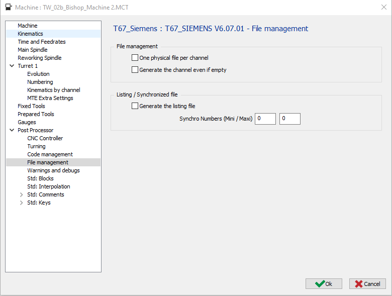
4 File management page
|
4.1 File Management – One physical File per Channel
|
Option |
File 1 |
File 2 |
|
|
O1000 (FIRST CHANNEL PROGRAM) … … M30
O1001 (SECOND CHANNEL PROGRAMM) … … M30 |
|
|
|
O1000 (FIRST CHANNEL PROGRAM) … … M30 |
O1001 (SECOND CHANNEL PROGRAMM) … … M30 |
4.2 File Management – Generate the channel even if empty
|
Option |
Result |
|
|
If a channel is empty no output of the program |
|
|
If a channel is empty, the program will be output (but empty (Just O1001 and M30 will be output) |
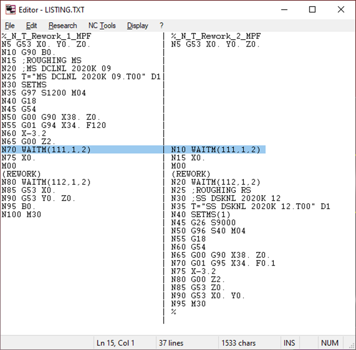
4.3 Listing / Synchronized File – Generate the Listing File
You need to set the Synchro Number mini & maxi to output the listing
|
Option |
Result |
|
|
Don’t generate the file to see the synchro between channels. |
|
|
Generate the file to see the synchro between channels. |
The file with the name Listing.TXT will be generated and shown.
|
Listing / Synchronized File – Synchro Numbers (Mini / Maxi)
Define here the synchronization Numbers (for example 500 – 540)
The post processor will search for the synchronizations numbers between these mini and maxi values to generate the Listing.TXT file.
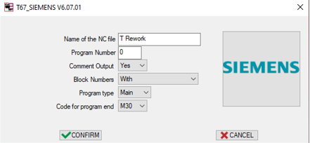
5 Launch page
|
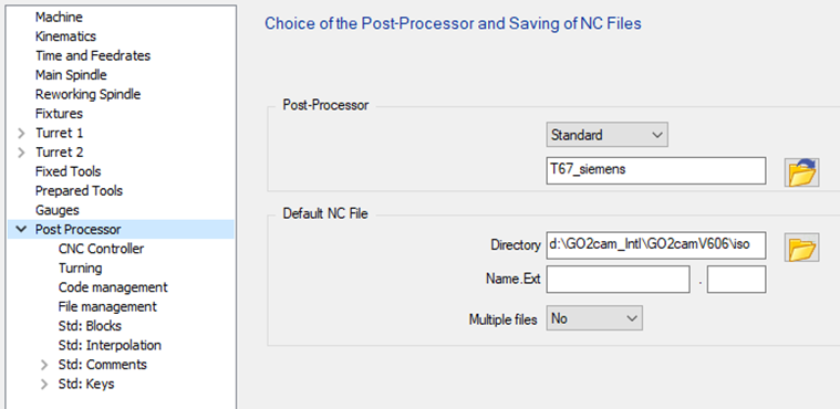
5.1 Name of the NC File : Define here the Name of the generated NC file.
The extension is to be defined in the MCF configuration.
5.2 Program Number : If 0 is defined, the program Number will be set to 1.
|
Option |
Result |
|
0 |
%MPF1 … |
|
“10” |
%MPF10 … |
|
“1234” |
%MPF1234 … |
5.3 Comment Output
|
Option |
Result |
|
No |
… T01 D01 M06 … |
|
Yes |
… ;FACING ;CNMG 04 T01 D01 M06 … |
5.4 Block Numbers
|
Option |
Result |
|
With |
%MPF1 N5 T01 D01 M06 N10 G00 X10 Z20 N15 Z10 … … N50 T02 D02 M06 N55 G00 X20 Z20 N60 Z10 … |
|
Without |
%MPF1 T01 D01 M06 G00 X10 Z20 Z10 … … T02 D02 M06 G00 X20 Z20 Z10 … |
|
Tool Change Only |
%MPF1 N5 T01 D01 M06 G00 X10 Z20 Z10 … … N10 T02 D02 M06 G00 X20 Z20 Z10 … |
5.5 Program Type
|
Option |
Result |
|
Main |
%MPF1 … … M30 |
|
Sub |
%SPF1 … … M17 |
5.6 Code for Program End :
|
Option |
Result |
|
M30 |
… M30 % |
|
M02 |
… M02 % |