Application of Users Holes
Users Holes in Design
The Users Holes command allows to define a hole in the Design environment, either on wireframe or solid geometry. Launching the command opens a dialog window giving access to 3 tabs; Holes Models, Normal and List of Operations. Holes Models: You will have access to the Standard or Specific user hole families created in the Users Holes Management command, with their defined models. The hole stages defined in the selected model are accessible under ‘Stage’ and their parameter can be modified in the table under. The greyed out values are the parameters set during creation. Normal: If you check the box to reorient the hole along the respective axis, you can only choose a value of -1, 0 or 1. For X and Y, this will determine the rotation of the hole by 45 degrees along that axis. For Z, the value is 1 by default. Change the value to -1 to invert the hole direction. List of Operations: The list of operations is automatically generated for the hole model. For detailed information click here. Parameters: A list of parameters defining each stage of the hole is available in tabular form . The last column is greyed out since it shows the initial value of the hole. The middle column is modifiable only if no values have been defined during the creation stage, else this is also greyed out. You have to ensure to fill all the parameters with ‘?' else, you won’t be able to generate the hole and will be prompted by a message ‘All the parameters of the hole are not filled’. | 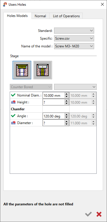 |
Users Holes in Holes Recognition
Function of Hole Recognition:o The hole recognition process serves two primary purposes:
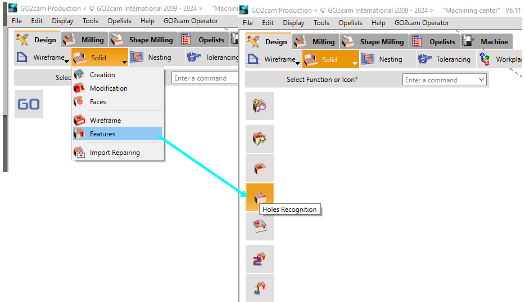
Accessing the Function:o To access the hole recognition function: Design>Solid>Features>Hole Recognition |
 |
 | |
Setting Parameters for Hole Recognition:
| |
Tolerance Distance |
|
Angle | The angle parameter helps identify the orientation of faces:
|
Maxi Diam of Holes |
|
 | Reset of the parameters to the default values |
Long Holes | The default value for this parameter is 7.0
|
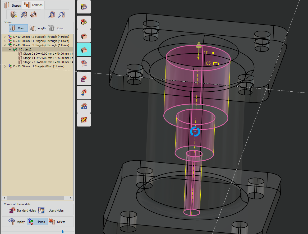
When applying user hole models to recognized shapes, GO2cam examines the topologies of the holes. It searches for compatible models across all families of models, including standard and specific ones, and presents them in a single list. Users can then select the most suitable model and apply it to the displayed pages. It’s advisable to avoid selecting holes with different topologies (such as varying numbers of stages or blind versus through holes). If there’s only one compatible model for a user hole, it is automatically applied without the usual confirmation prompt. Prior to using this behaviour, ensure that the ‘Automatic applying if one available model’ option is validated in Tools/Options/Holes. The “Shapes strictly identical” option allows you to adjust the number of models presented. When this option is unchecked, the list includes models that match the hole’s shape, even if they have additional features like fillets and chamfers that are not part of the original shape. This provides flexibility in selecting the most suitable model for your needs. | |
Displaying Holes - When applying a model to selected shapes, you have the option to display or hide the created holes in the list. | |
Plane Creation - When applying a standard or user-defined hole, a geometrical plane is generated if no existing plane corresponds to the recognized direction. To assist your decision-making, consider the following scenarios: | |
Parallelepipedal Part: If your part has a parallelepipedal shape, it’s advisable to check the box. In this case, only a few planes will be created, corresponding to the faces of the part. | 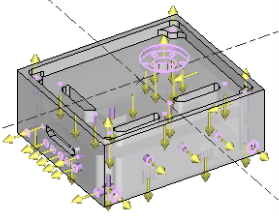 |
Part of Revolution: For parts with a rotational symmetry (such as cylindrical or conical shapes), avoid creating additional planes. Each hole will have its own unique plane. This approach prevents the generation of hundreds of unnecessary planes. When machining on a rotary table, referencing each hole to its specific machining plane is essential for optimizing rapid hole motions. | 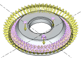 |
Deletion Function - This function allows you to cancel the most recent creation action. | |
|  |
| 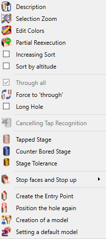 |
Through all | For GO2cam, if a hole goes through a pocket or is cut by another hole, it is considered as a through hole. We can link together parts of co-axial holes in the function Union of the table Shapes. Here, you inform GO2cam that the hole is going through all the material, which means until the stock, whatever is its shape, and whatever is the length of the hole. Be careful with the stock definition when you use this option. | |
 | Force to ‘through’ | When a hole is recognized as blind, we can force the type so that it is considered as through. In this case, we can set it ‘Through’ again with the same function. You can give manually to a hole the notion of ‘Long hole’, even if it does not correspond to the ratio defined at the launching of the holes recognition. |
Long hole | ||
Cancelling Tap Recognition | When a part is read under the CAD format fte, the holes features are directly recognized in GO2cam. With this function, you can manually cancel this recognition and transform a tapped hole into a smooth hole. | |
 | Tapped Stage | You can give a quality to smooth holes: tapped, counter bored or reamed. For each of the possibilities, a dialog box is open where you have to fill specific parameters according to the type of hole stage chosen. |
 | Counter Bored Stage | |
 | Stage Tolerance | |
 | Creation of a Model | This function is very important for a GO2cam user. By clicking ‘Creation of a model’, you create a new user hole model based on the shape and dimensions of the selected hole. Furthermore, this new model is automatically given to the shape used for its creation. All the data are recovered for the creation (through or blind, number of stages, chamfers, and other dimensions), you simply need to adjust these values and define an operation list to this model. This function enables you to enhance very fast your library of user holes models. A whole chapter of this document is dedicated to user model creation, please read next page. |
 | Setting a default Model | Here, you do not create a model, but you apply directly a default model according to the shape and dimensions of the selected hole. |
After identifying the holes, you can proceed to the milling editor. There, you’ll have the option to machine the holes either in automatic mode or manual mode.
Automatic The software will handle the machining process based on predefined rules and parameters. It will efficiently drill the holes without manual intervention.
Manual Holes: If you prefer more control or need to adjust specific parameters, switch to manual mode. Here, you can fine-tune hole machining settings, such as diameter, direction, and length, according to your requirements.
