
Introduction
This page explains how to create a chuck for turn machine.
|
▶️ Watch a video at the bottom of page: Click here |
|
The creation process for tools, symbols, machine, etc. has become more fluid with the interactive system of axes.
|
▶️ Watch a video on the process creation. 
|
Creation of Chuck
|
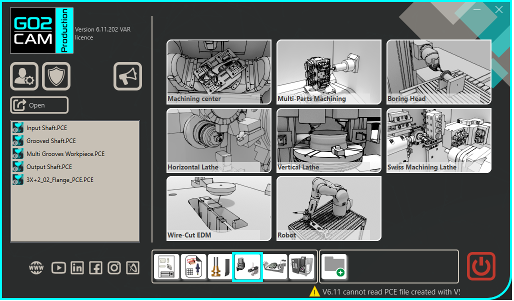
Select the “Clamping / Toolholders” module in the Homepage.
|
|
|
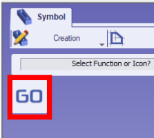
Click the GO button |
|
|
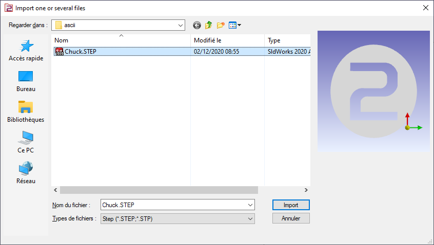
Select the file to import |
|
|
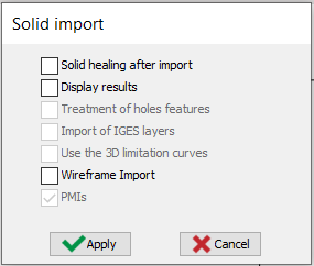
Select the import option to be applied to the solid. Click “Apply” |
|
|
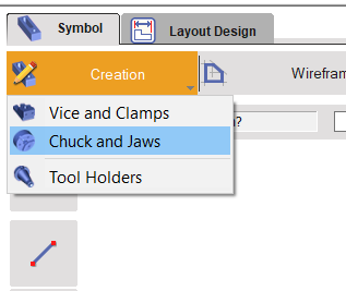
Click on the tab “Creation” then “Chuck and Jaws” menu |
|
|
Click the command to create system of axis |
|
|
Select the tool to define the position of system of axis |
|
|
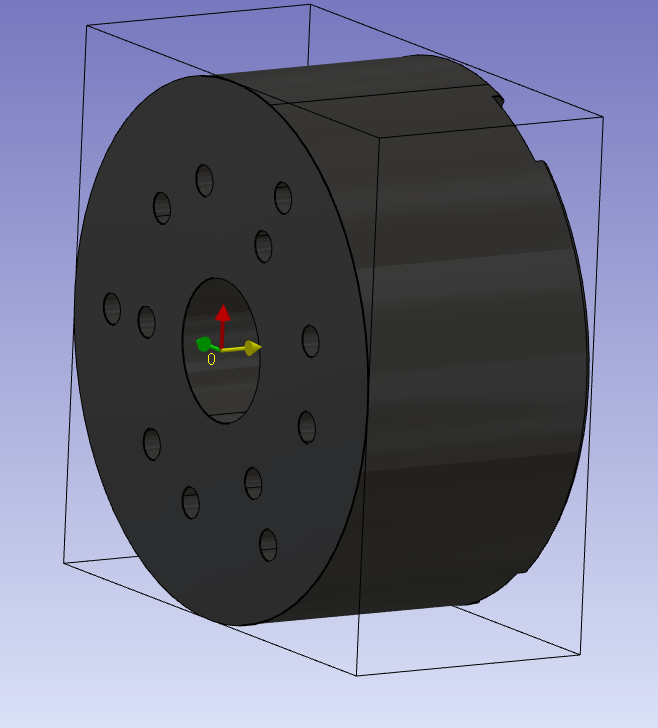
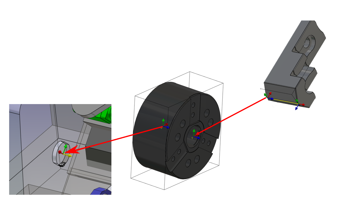
Define the system of axis 0.
This system of axis will be the mounted point of the chuck on the work assembly support of the machine.
The Z axis define the rotation axis.
|
|
|
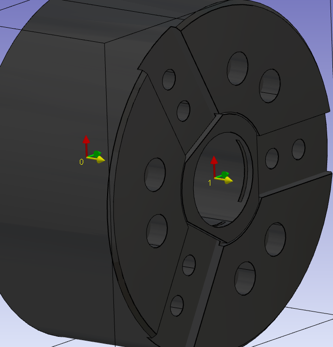
Do the same command to create the system of axis 1.
The origin position will define the face where the jaws will be mounted. The Z axis must the same than the system of axis 0. The X-axis will be aligned with the X-axis of the turning plane. It will also define the positioning of the first jaw. |
|
|
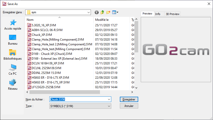
Save the file in the user’s symbol folder for use in GO2cam. |
|
Key points
-
System of axis 0 is the mounted point on the work assembly support.
-
System of axis 1 define where is mounted the first jaw.
-
The Z axis of the two systems of axis are oriented in the revolution axis of machine.
|
▶️ Watch a video about Chuck:
|