
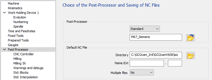
General Information
|
The standard has three configuration pages to manage all options available. The first page “CNC Controller” is about CNC options. The second page “Milling” allows to adapt the output for Milling, tools, coolant and origins. The third page “Milling” is about 5 axis parameters. |
|
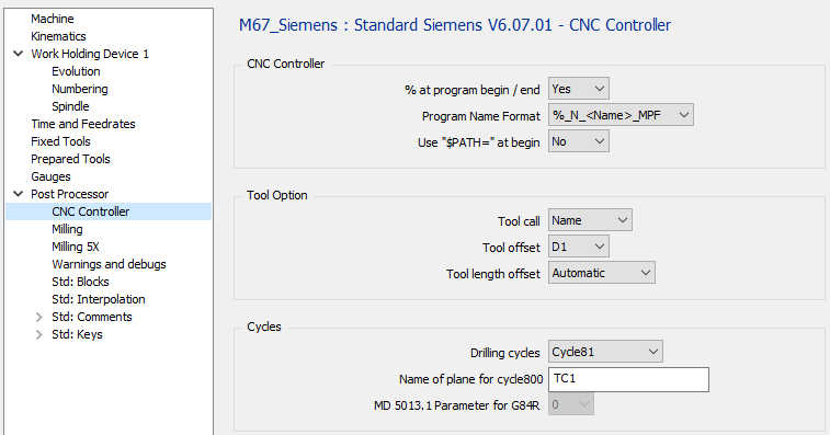
1 CNC Controller page
|
1.1 CNC Controller - % at program begin / end
|
Option |
Result |
|
No |
N5 G00 G53 Z0 … … M30 |
|
Yes |
% N5 G0 G53 Z0 … … M30 % |
1.2 CNC Controller - Program Name Format
|
Option |
Result |
|
%_N_<name>_MPF |
%_N_PROG_MPF N5 G00 G53 Z0 … … |
|
%MPF<number> |
%MPF1 N5 G00 G53 Z0… … … |
|
Without |
N5 G00 G53 Z0 … … |
1.3 CNC Controller – Use “$PATH=” at Begin
This option is available only if %_N_<name>_MPF is used
|
Option |
Result |
|
No |
%_N_PROG_MPF N5 G00 G53 Z0 … … |
|
Yes |
%_N_PROG_MPF ;$PATH=/_N_PART_DIR N5 G00 G53 Z0… … … |
1.4 Tool Option – Tool Call
|
Option |
Result |
|
Number |
… … T01 M06 … … |
|
Name |
… … T=”MILL_D10” M06 … … |
1.5 Tool Option – Tool Offset
|
Option |
Result |
|
D1 |
… … T01 D01 … … T02 D01 … … |
|
D |
… … T01 D01 … … T02 D02 … … |
1.6 Tool Option – Tool Length Offset
|
Option |
Result |
|
Automatic |
… … T01 D01 Z20 … … |
|
G43 H.. |
… … T01 G43 H01 Z20 … … |
1.7 Cycles – Drilling Cycles
|
Option |
Result |
|
Cycle81 |
… MCALL CYCLE81(2,0,2,-10.412,) … MCALL … |
|
Fanuc Like |
… G81 G94 Z-10.412 R2. F606 … G80 … |
|
G81 R… |
… R2=0 R3=10.412 R10=2 G81 … G80 … |
1.8 Cycles – Name of Plane for CYCLE800
|
Option |
Result |
|
“TC1” |
… CYCLE800(1,”TC1”,0,39,0,0,0,180,-90,0,0,0,0,-1) … |
|
“TABLE” |
… CYCLE800(1,”TABLE”,0,39,0,0,0,180,-90,0,0,0,0,-1) … |
1.9 Cycles – MD 5013.1 Parameter for G84 R
This defines if the G84 R is used with or without encoder. This is linked to the “MD 5013.1” machine parameter. This changes the R6 and R7 values.
Works only for non Rigid tapping.
|
Option |
Result |
|
0 |
… R2=0 R3=6 R4=0 R6=4 R7=3 R9=0.8 R10=2 R11=0 G84 … G80 … |
|
1 |
… R2=0 R3=6 R4=0 R6=0 R9=0.8 R10=2 R11=0 G84 … G80 … |
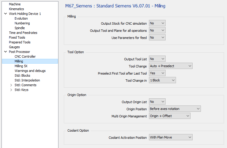
2 Milling page
|
2.1 Milling – Output Stock for CNC Simulation
|
Option |
Result |
|
No |
%_N_PROG_MPF … |
|
Yes |
%_N_PROG_MPF WORKPIECE(,””,,”BOX”,112,1-39,0,-42.5,-35,42.5,35) … |
2.2 Milling – Output Tool and Plane for all operations
|
Option |
Result |
|
No |
;OP 1 WITH TOOL 1 AND PLANE 1 T01 D01 M06 CYCLE800(1,”TC1”,0,39,0,0,0,90,-90,0,0,0,0,-1) … … ;OP 2 WITH TOOL 1 AND PLANE 1 … … |
|
Yes |
;OP 1 WITH TOOL 1 AND PLANE 1 T01 D01 M06 CYCLE800(1,”TC1”,0,39,0,0,0,90,-90,0,0,0,0,-1) … … ;OP 2 WITH TOOL 1 AND PLANE 1 T01 D01 M06 CYCLE800(1,”TC1”,0,39,0,0,0,90,-90,0,0,0,0,-1) … … |
2.3 Milling – Use Parameters for Feed
|
Option |
Result |
|
No |
T01 D01 M06 G00 X.. Y.. Z.. Z-.. F160 G1 X.. Y.. F200 … … |
|
Yes |
R21 = 200 R22 = 160 T01 D01 M06 G00 X.. Y.. G43 H1 Z.. Z-.. F=R22 G01 X.. Y.. F=R21 … … |
2.4 Tool Option – Output Tool List
|
Option |
Result |
|
No |
%_N_PROG_MPF … … |
|
Yes |
%_N_PROG_MPF ;START TOOL LIST ;T01 END MILL D10 ;T02 DRILL D08 … ;END TOOL LIST … … |
2.5 Tool Option – Tool Change
|
Option |
Result |
|
Manual |
… ;END MILL D10 M0 … |
|
Automatic |
… ;END MILL D10 T01 D01 M06 … |
|
Auto + Preselect |
… ;END MILL D10 T01 D01 M06 T02 … |
2.6 Tool Option – Preselect First Tool after Last Tool
|
Option |
Result |
|
No |
;FIRST OPERATION T01 D01 M06 T02 … … ;LAST OPERATION T05 D01 M06 … … M30 |
|
Yes |
;FIRST OPERATION T01 M06 T02 … … ;LAST OPERATION T05 D01 M06 T01 … … M30 |
2.7 Tool Option – Tool Change in
|
Option |
Result |
|
1 Block |
… … T01 D01 M06 … … |
|
2 Blocks |
… … T01 D01 M06 … … |
2.8 Origin Option – Output Origin List
|
Option |
Result |
|
No |
%_N_PROG_MPF … … |
|
Yes |
%_N_PROG_MPF ;START ORIGIN LIST ;G54 ;G55 ;END ORIGIN LIST … … |
Origin position
|
Option |
Result |
|
After axes Rotation |
|
|
Before Axes rotation |
|
2.9 Origin Option – Multi Origin Management
|
Option |
Result |
|
Origin Only |
% O1000 … G54 … |
|
Origin + Offset |
% O1000 … G54 TRANS X10 Y20 Z10 … |
Without MTE :
If the option is set to “Origin Only” for each origin define on the part, we will output a different G code, G54, then G55, G56 … It means you are limited by the number of origin managed by the CNC. If you can have more origin, you must use the second option “Origin + Offset”
If the option is set to “Origin + Offset” it will only output G54 and offset with G52
With MTE :
The origin can be define in the name of the origin with the following syntax “$G54_”. It means G54 will be used in the NC program. If there is no decoded name define, it will output the default origin G54.
If you use “Origin + Offset”, you must use only one origin for all your operation because all the offset are compute from the reference plane origin or single origin.
You can add every text after the underscore to recognized your offset “$G54_Up”, “$G54_Right”, …
With 5 axis machine :
The origin offset is output with the tilted plane function G68.1 if is set to be output. So it means no G52 is output.
2.10 Coolant Option – Coolant Activation Position
|
Option |
Result |
|
With Spindle |
… … T01 D01 M06 S800 M03 M08 G00 X.. Y.. Z… … … |
|
With Plane Move |
… … T01 D01 M06 S800 M3 G00 X.. Y.. M8 Z.. … … |
|
With Plunge Move |
… … T01 D01 M06 S800 M03 G00 X.. Y.. Z.. M08 … … |
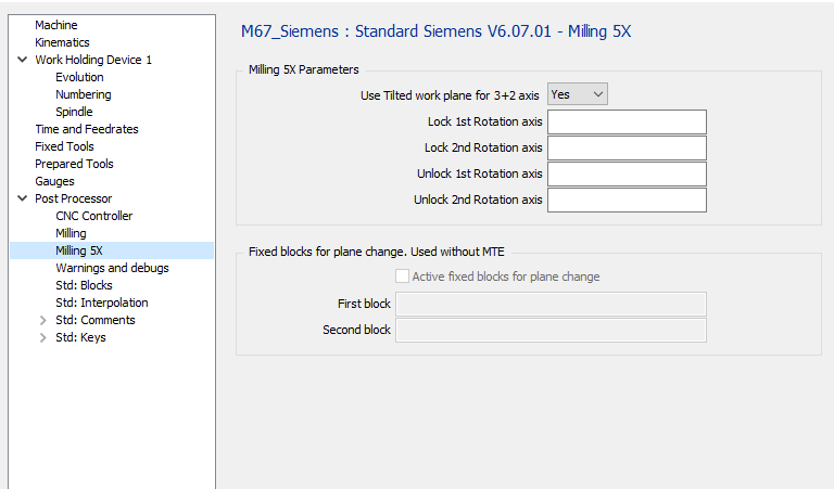
3 Milling 5X
|
3.1 Milling 5X Parameters – Use Tilted work Plane for 3+2 Axis
|
Option |
Result |
|
No |
… … T01 D01 M06 C180 A-90 … … |
|
Yes |
… … T01 D01 M06 CYCLE800(1,“TC1 »,0,39,0,0,0,180,-90,0,0,0,0-1) … … |
3.2 Milling 5X Parameters – Lock 1st Rotation Axis
|
Option |
Result |
|
empty |
… … C180 … … |
|
“M10” |
… … C180 M10 … … |
3.3 Milling 5X Parameters – Lock 2nd Rotation Axis
|
Option |
Result |
|
empty |
… … B-90 … … |
|
“M12” |
… … B-90 M12 … … |
3.4 Milling 5X Parameters – Unlock 1st Rotation Axis
|
Option |
Result |
|
empty |
… … C180 … … |
|
“M11” |
… … M11 C180 … … |
3.5 Milling 5X Parameters – Unlock 2nd Rotation Axis
|
Option |
Result |
|
empty |
… … B-90 … … |
|
“M13” |
… … M13 B-90 … … |
3.6 Fixed blocks for plane change - Active fixed blocks for plane change
This option is used only if there is no kinemac defined in the machine configuration.
|
Option |
Result |
|
check |
The fixed blocks defined will be output if there is a plane change |
|
uncheck |
No block will be output if there is a plane change. |
3.7 Fixed blocks for plane change - First and second
|
Option |
Result |
|
Empty |
… … |
|
“G0 Z100” |
… … G00 Z100 … … |
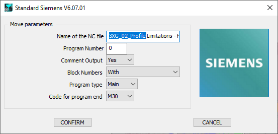
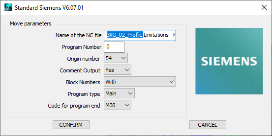
4 Launch page
|
With machine kinematic defined |
Without machine kinematic defined |
|
|
4.1 Name of the NC File
Define here the Name of the generated NC file. The extension must to be defined in the MCF configuration.
4.2 Program Number
If 0 is defined, the program Number will be set to 1.
|
Option |
Result |
|
0 |
%MPF1 … … |
|
“10” |
%MPF10 … … |
|
“1234” |
%MPF1234 … … |
4.3 Origin Number
This parameter is use only if kinematic is not defined in the machine file. The parameter defines the first origin used in the NC program.
If the parameter to treat multi origin is set on “Origin Only” the origin number is incremented when a plane changes.
|
Option |
Result |
|
54 |
%MPF1 T01 M06 G54 … |
|
55 |
%MPF1 T01 M06 G55 … |
4.4 Comment Output
|
Option |
Result |
|
No |
… … T01 D01 M06 … … |
|
Yes |
… … ;FACING ;END MILL D12 T01 D01 M06 … … |
4.5 Block Numbers
|
Option |
Result |
|
With |
… N5 T01 D01 M06 N10 G00 X.. Y.. N15 G43 Z.. H1 … … N50 T02 D01 M06 N55 G00 X.. Y.. N60 G43 Z.. H2 … … |
|
Without |
… T01 D01 M06 G0 X.. Y.. G43 Z.. H1 … … T02 D02 M06 G00 X.. Y.. G43 Z.. H2 … … |
|
Tool Change Only |
… N5 T01 D01 M06 G00 X.. Y.. G43 Z.. H1 … … N10 T02 D01 M06 G00 X.. Y.. G43 Z.. H2 … … |
4.6 Program Type :
|
Option |
Result |
|
Main |
%MPF1 … … M30 |
|
Sub |
%SPF1 … … M17 |
4.7 Code for Program End
|
Option |
Result |
|
M30 |
… … M30 |
|
M02 |
… … M02 |