
This page is divided into 2 parts.
-
The first section describes some rules and recommendations to be followed for the programming of a part.
-
The second section describes the programming process.
Rules and Recommendations
|
Load the machine It is recommended in GO2cam to have the machine loaded first, ideally with an FMO. Due to the complexity of these machines, typically in machine shops, the settings and tool positioning in the machine will be changed very rarely. Having the FMO of the actual mounted tool will ensure proper machining cycles definition. |
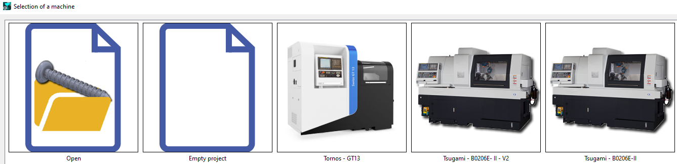
On opening the module, this window is prompted where we can select a machine if we have one defined, as the first step. A blank project is opened with the machine already loaded. |
|
Part positioning The position of the part is highly dependent on the machine being used; its kinematics, available machining length, racks positioning and tools loaded. Generally, majority of turning operations is to be done on the main spindle. Any outside turning operation on the rework spindle is to be done with a boring cutter. |
|
|
Machining practice Programming the machining cycles is no different to Turnmill operations. Where is differs is the geometry on which it is applied. While for a turning cycle (roughing/finishing) the operation can be applied on the full length of the machinable part, this is to be avoided for Swiss type machining. The machining is carried out in such a way so as to prevent the machined bar from retracting too much into the guide bush.
|
|
|
As such, machining is done by splitting the part into several sections. The maximum operations applicable are then programmed section by section. In GO2cam, the Slice the part command in provided to assist in the sectioning of the part and on application of an opelist, the operations are calculated for each section. On the machine, the operations are carried out progressively as the material advances. |
|
|
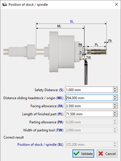
Stock/Spindle Positioning The position of the stock is important so as to optimize the motion of the bar throughout the machining process. Typically it is recommended to have the value of the Stock Overrun be at least the value of SL as shown on the right. The distance values are automatically read from the project file and the machine kinematics. The advantage of using an FMO is also projected here where the width of the parting tool and its allowance can be automatically read and the recommended SL value is proposed. For more details on the main chuck positioning, click here. |
|
Process
The general programming process in GO2cam is described below:
To begin programming a Swiss machining center, the first step is to select the specific machine model. The programming process varies depending on the machine's configuration. The machine file includes an .FMO file, signifying pre-mounted tools. Using .FMO files is the recommended practice in GO2cam for Swiss machining.
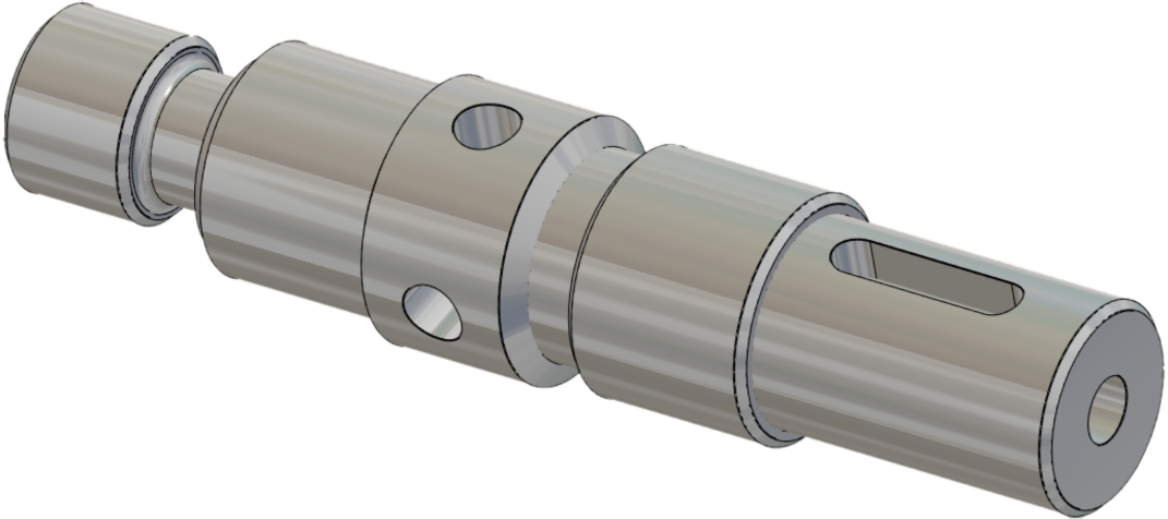
Once the machine file is loaded, the next step is to import the workpiece, making sure it's correctly oriented. To prevent collisions and ensure sufficient clearance during machining, we'll create a safety area around the workpiece. |
|
Slicing divides the workpiece into smaller, manageable sections, enabling precise control and efficient toolpath generation. Each zone should be machined gradually, as determined by the Z-value. To create slices on the workpiece, we need to specify the desired slice length. In this case, we'll use a 25 mm slice length. This will divide the workpiece into multiple zones. We can adjust the position of these slices manually by inputting values or by directly moving the white line on the interface. |
|
Applying an auto-opelist to the sliced workpiece. The opelist automates operations and cutting conditions. |
|
|
|
Simulating the MTE (Machine Tool Equipment) can help verify the toolpaths, speeds, and feeds, ensuring that the tools are used effectively. |

|
|
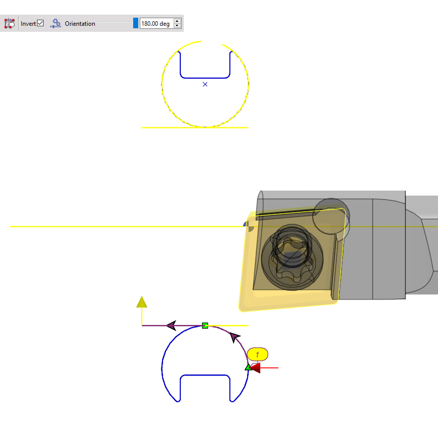
Program operations on X minus Depending on the tool orientation and the part size, axial milling on the C axis is only possible if the part is properly positioned relative to the tool.
|

|
Special Case
|
Program operations with tool on lower rack Swiss Machines generally have multiple racks with some tools mounted on lower/upper/side racks. For tools on the upper rack, the usual programming principles works fine. This is not the case for tools on the lower rack which can generate bad toolpaths with collisions. An example is shown in the video and 3 solutions are discussed: |
|
|
1/ Change tool position to upper rack The first solution is to simply move the required tool to the upper rack if feasible and program as usual. |
|
|
2/ Program with lower silhouette To avoid any issue, use the lower silhouette for profile selection. Also ensure the orientation of the tool and the tool cycle type is changed accordingly so as the cycle is computed. |
|
|
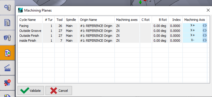
3/ Change the Machining Planes in MTE - Tooling In the Machining Planes command, change the machining axes for the required cycles to X- or X+ accordingly to have the system automatically compute the accurate toolpaths.
|
|