
Introduction
This page explains how to create a single milling tool holder.
|
▶️ Watch a video at the bottom of page: Click here |
|
The creation process for tools, symbols, machine, etc. has become more fluid with the interactive system of axes.
|
▶️ Watch a video on the creation process. 
|
Creation of mill tool holder
|
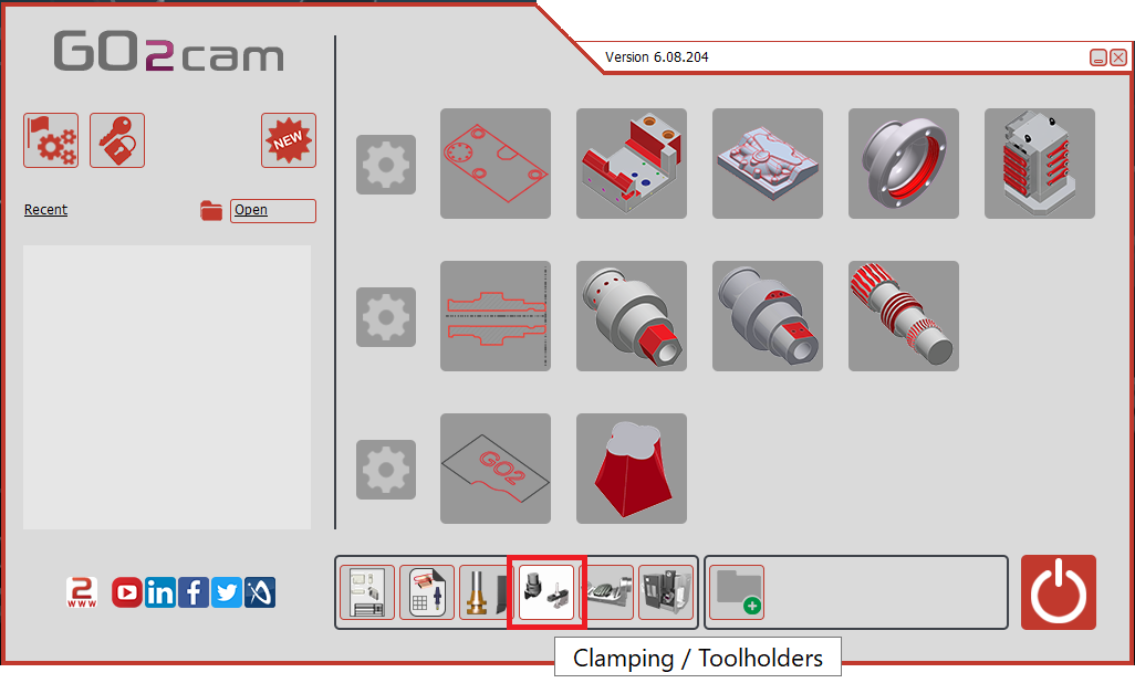
Select the “Clamping / Toolholders” module in the Homepage.
|
|
|
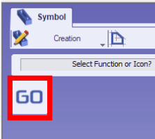
Click the GO button |
|
|
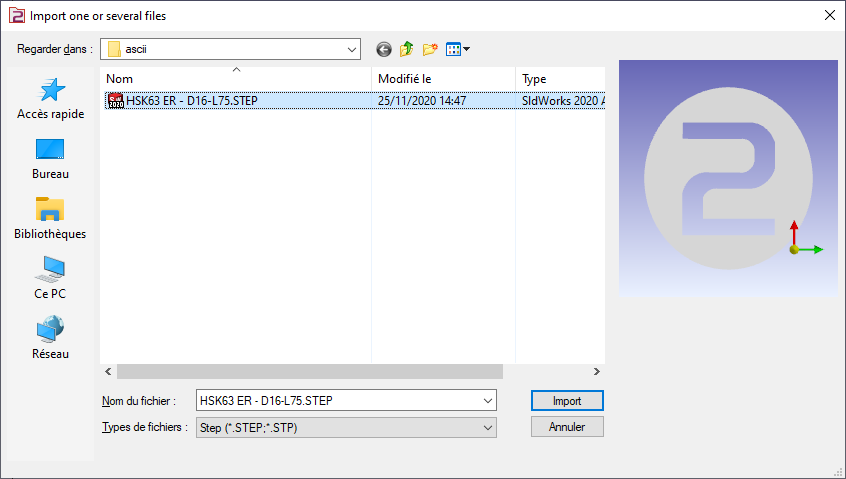
Select the file to import |
|
|
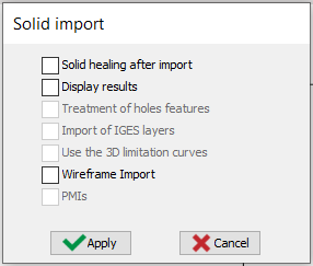
Select the import option to be applied to the solid. Click “Apply”
The axis system can also be imported from solid CAD files by activating the Wireframe Import option. This feature is particularly useful for creating holders by importing STEP files from databases such as Sandvik or Iscar. It allows the recovery of the axis systems for positioning inserts, as illustrated for the turning tool in the image on the right. |
|
|
|
|
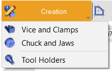
Click on the tab “Creation” then “Tool Holders” menu |
|
|
Click the command to create system of axis |
|
|
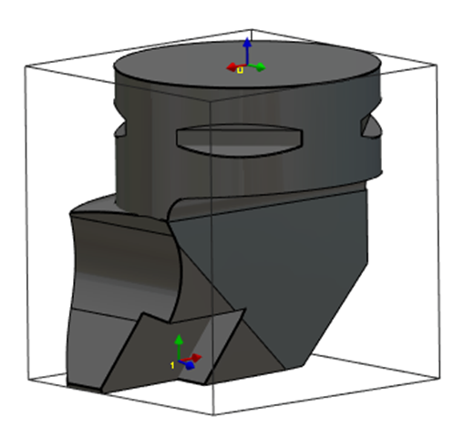
Select the tool to define the position of system of axis |
|
|
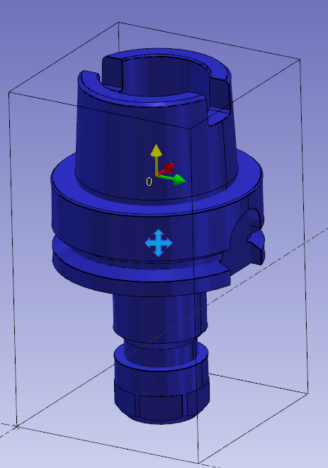
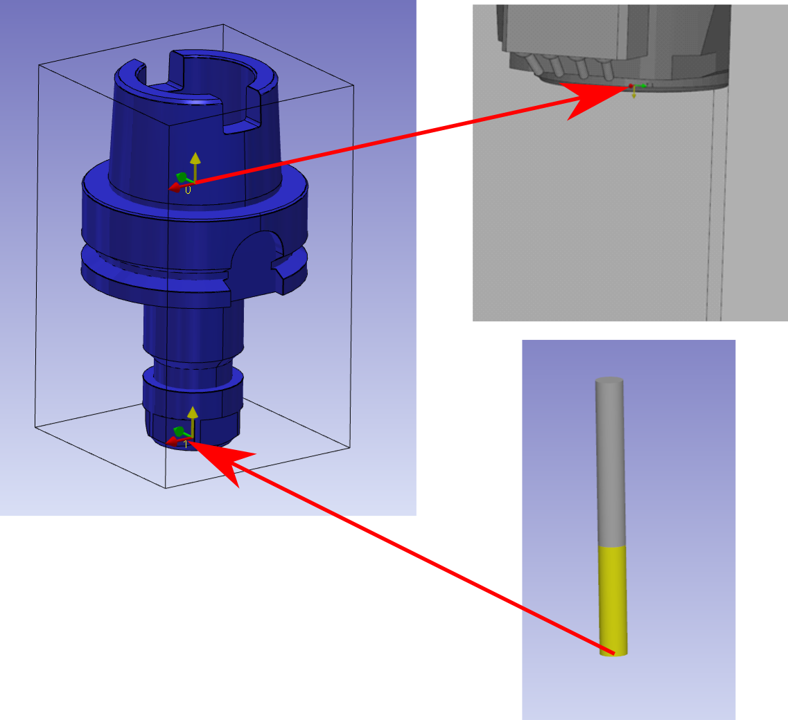
Select the surface/point that will be the point origin of system of axis. The system of axis referenced 0 define the point that will mounted on the previous element. The previous element can be a tool support or another toolholder component. There are two methods to add the axis system: Use Ctrl + Shift to select the profile. Or, select the surface of the tool holder, as indicated by the red arrow. Ensure that the view is sufficiently zoomed in when selecting the face. |
|
|
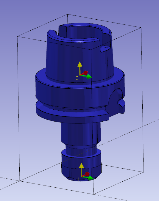
Do the same command to create the system of axis 1. It will be the mounted position for the tool or next element.
|
|
|
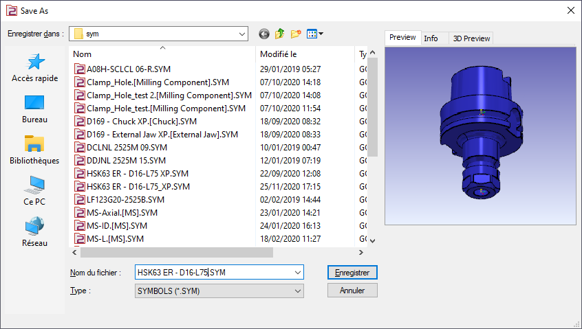
Save the file in the user’s symbol folder for use in GO2cam. |
|
Key points
-
System of axis 0 is the mounted point on the spindle.
-
System of axis 1 is the point where the tool tip is mounted.
-
The Z axis of the two systems of axis are oriented into the spindle.
|
▶️ Watch a video about Single Mill Toolholder:

|