We can consider 2 ways to create toolholders in GO2cam:
-
by drawing toolholders in ‘Forming Tools/Tools Libraries’
-
by importing holders from CAD in ‘Clamping / Toolholders’
Drawing Toolholders
This method is available in the environment ‘Forming Tools/Tools Libraries’. It is more and more rare, due to the better quality of CAD exchange those last years.
But you can still draw and create 3 types of toolholders:
-
create milling toolholders by revolution of a 2D profile,
-
create turning toolholders by revolution of a 2D profile,
-
create turning toolholders by extrusion of a 2D profile.
For each of them, you need to draw first the 2D geometry, then define it as a profile. Once the profile selected, the toolholder is created and saved as a *.SYM file.
|
Rules of creation:
|
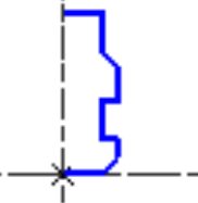
Toolholder by Revolution |
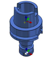
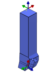
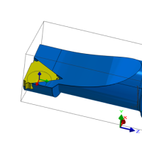
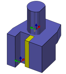
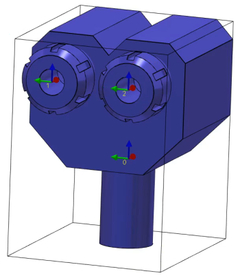
Importing Toolholders
This method of importing toolholders from CAD softwares is much more frequent.
|
The creation process for tools, symbols, machine, etc. has become more fluid with the interactive system of axes.
|
▶️ Watch a video on the creation process. 
|
Here are several standard examples of toolholders imported from CAD; we describe the process in details in the following pages: