
Introduction
This page explains how to create a single turn tool holder.
|
▶️ Watch a video at the bottom of page: Click here |
|
The creation process for tools, symbols, machine, etc. has become more fluid with the interactive system of axes.
|
▶️ Watch a video on the creation process. 
|
Creation of turn tool holder
The sample is done for a left insert holder. You will find the difference between right and left insert holder in the chapter ‘Difference between tool holder for right or left insert holder’ below.
|
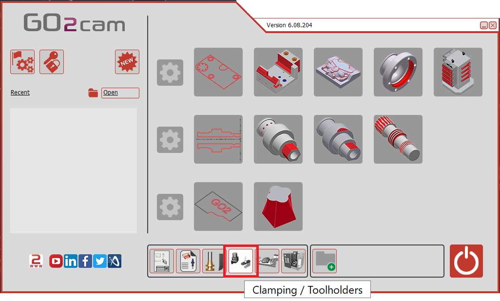
Select the “Clamping / Toolholders” module in the Homepage.
|
|
|
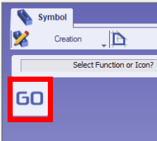
Click the GO button |
|
|
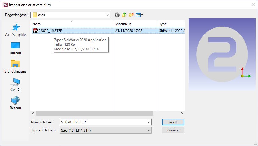
Select the file to import |
|
|
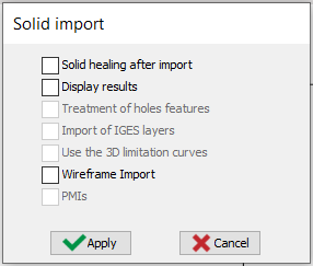
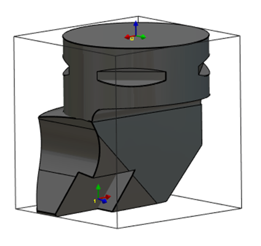
Select the import option to be applied to the solid. Click “Apply”
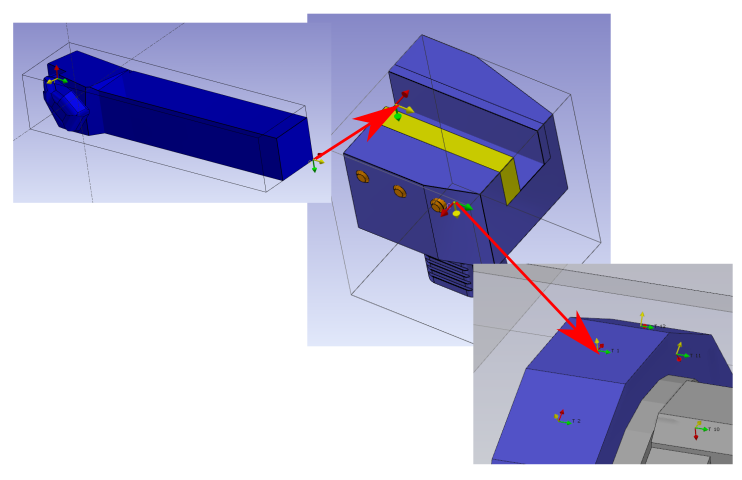
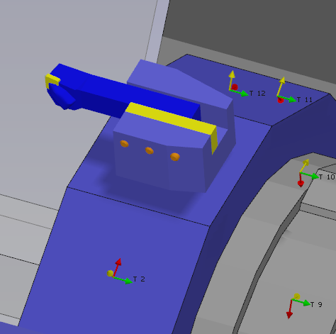
The axis system can also be imported from solid CAD files by activating the Wireframe Import option. This feature is particularly useful for creating holders by importing STEP files from databases such as Sandvik or Iscar. It allows the recovery of the axis systems for positioning inserts, as illustrated for the turning tool in the image on the right. |
|
|
|
|
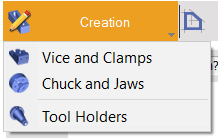
Click on the tab “Creation” then “Tool Holders” menu |
|
|
Click the command to create system of axis |
|
|
Select the tool to define the position of system of axis |
|
|
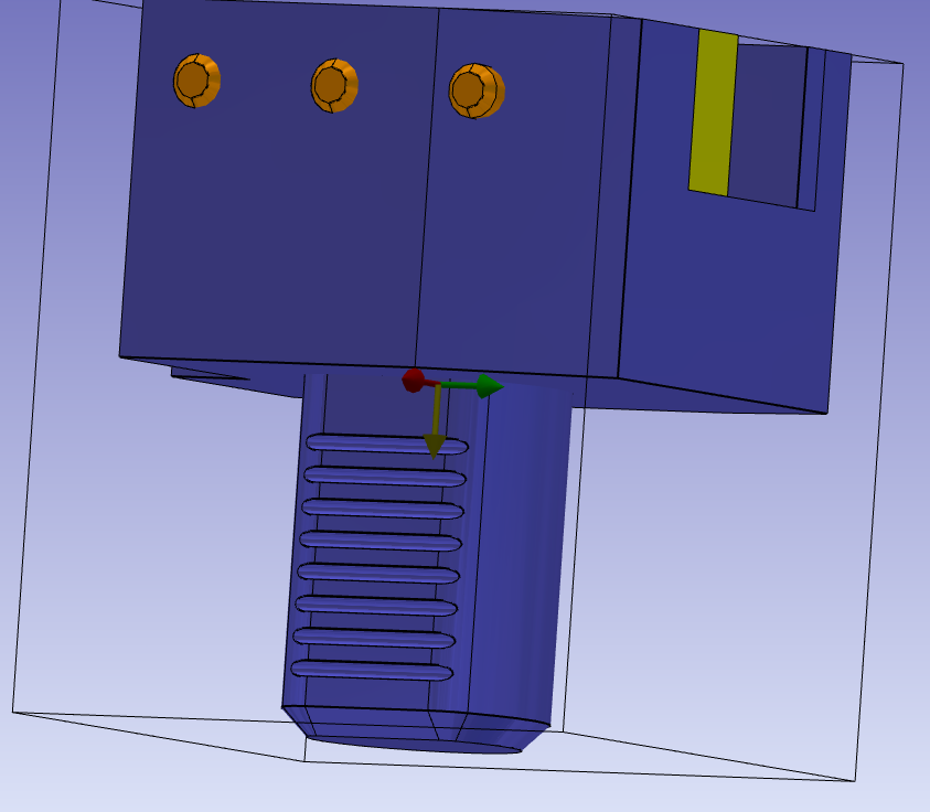
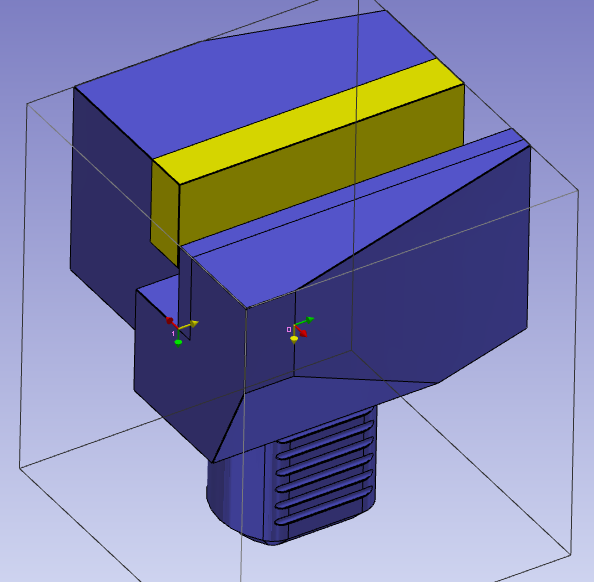
Select the faces to orient Z and X axes and point to define the system of axis. The system of axis referenced 0 define the point that will mounted on the previous element. The previous element can be a tool support or another tool holder component. The center of a circle can be selected by pressing CTRL + SHIFT and then clicking on the arc edge. Check the “change of direction” command to change the Z direction. |
|
|
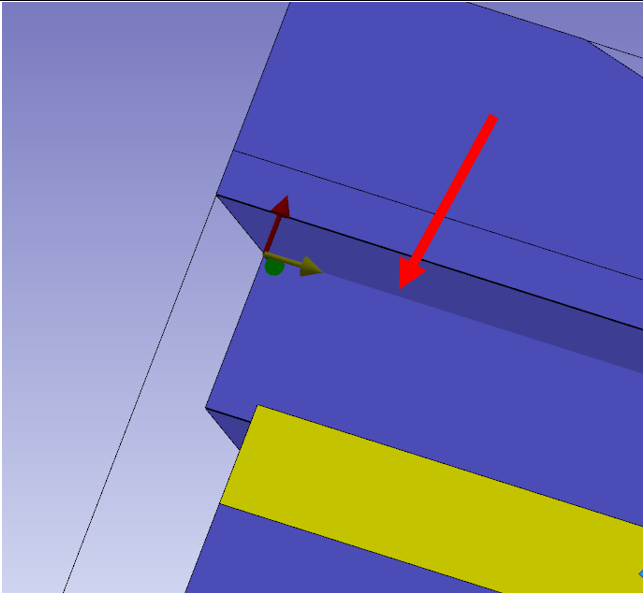
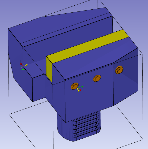
Do the same command to create the system of axis 1. It will be the mounted position for the tool or next element. However, for the change of Z direction click on the selection of insertion axis and select the line shown by red arrow. Then place the axis at the correct point using the selection of origin command icon. |
|
|
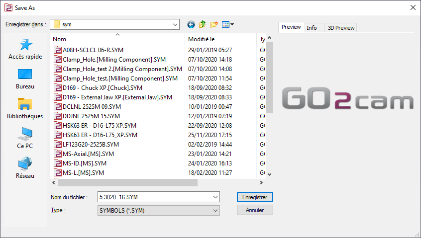
Save the file in the user’s symbol folder for use in GO2cam. |
|
Difference between tool holder for right or left insert holder
The difference is only for the position of the system of axis 1.
|
Tool holder for left insert holder |
|
|
Tool holder for right insert holder |
|
Key points
-
System of axis 0 is the mounted point on the turret or on tool holder. The system of axis 0 is in accordance with the system axis of another tool holder.
-
If the holder is mounted on a tool support on a machine, the system of axis 0 is symmetric regarding the tool support.
-
The system of axis 1 is the point where the next solid will be mounted. It is according with the system of axis of the next element.
|
▶️ Watch a video about Single turn tool holder:
|