
Introduction
The target of this page is to explain how to create a turn insert holder.
|
▶️ Watch a video at the bottom of page: Click here |
|
The creation process for tools, symbols, machine, etc. has become more fluid with the interactive system of axes.
|
▶️ Watch a video the creation process. 
|
Creation of turn insert holder
The explanation are done for a left insert tool holder. The steps to create a right insert tool holder are the same. There are examples of both in ‘Difference between right and left insert holder’ in this page.
|
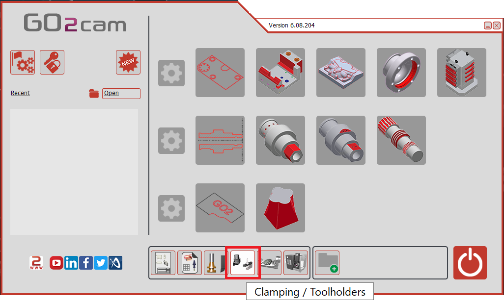
Select the “Clamping / Toolholders” module in the Homepage.
|
|
|
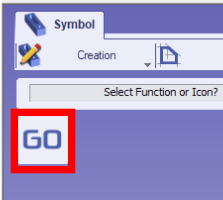
Click the GO button |
|
|
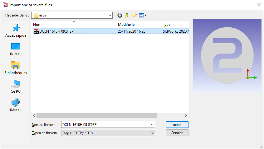
Select the file to import |
|
|
Select the import option to be applied to the solid. Click “Apply”
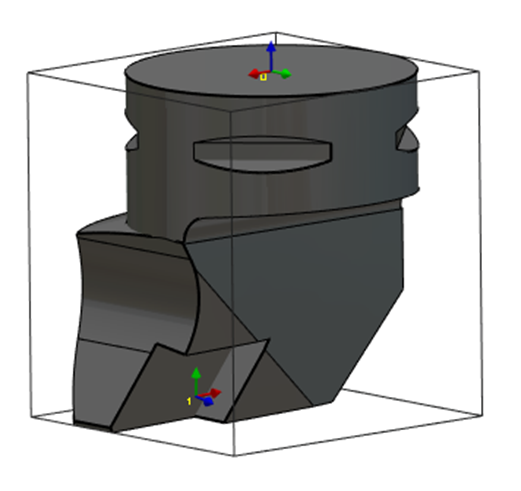
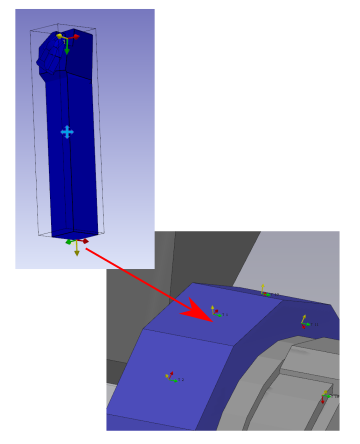
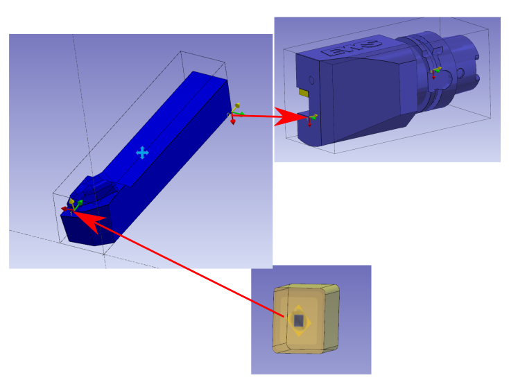
The axis system can also be imported from solid CAD files by activating the Wireframe Import option. This feature is particularly useful for creating holders by importing STEP files from databases such as Sandvik or Iscar. It allows the recovery of the axis systems for positioning inserts, as illustrated for the turning tool in the image on the right. |

|
|
|
|
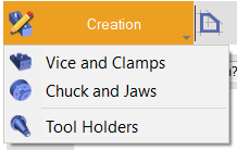
Click on the tab “Creation” then “Tool Holders” menu |
|
|
Click the command to create system of axis |
|
|
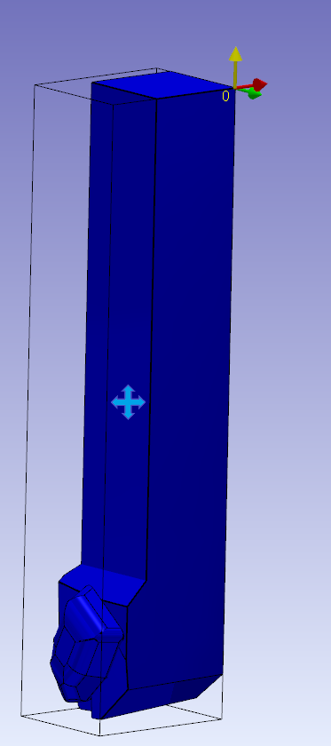
Select the tool to define the position of system of axis |
|
|
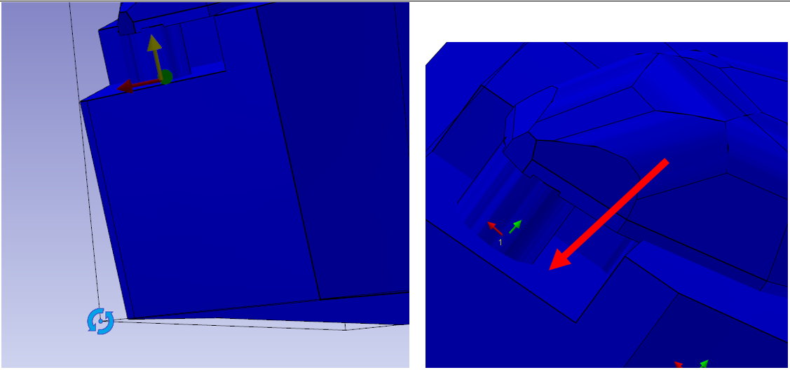
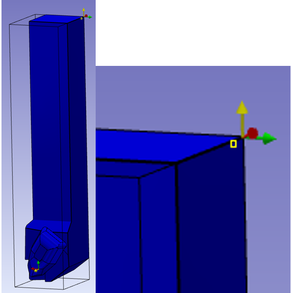
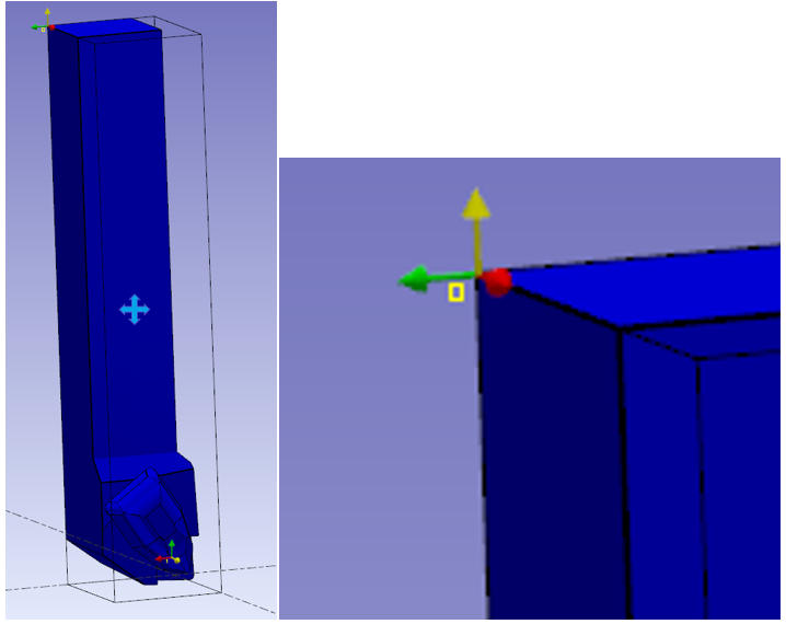
Select the faces to orient Z and X axes and point to define the system of axis. The system of axis referenced 0 define the point that will mounted on the previous element. Click on the axis creation icon and position it and check the “change of direction” command to change the Z direction. The previous element can be a spindle or another tool holder component. |
|
|
Do the same command to create the system of axis 1. It will be the mounted position for the insert. Be careful to select the correct Z axis and X axis and center of insert. |
|
|
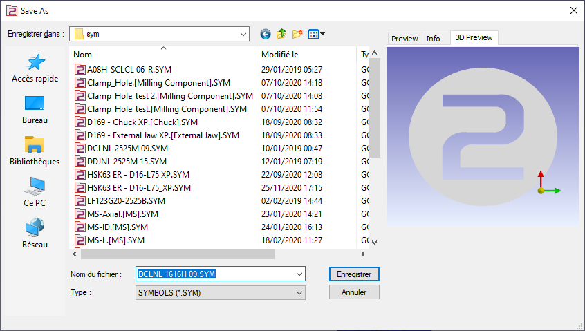
Save the file in the user’s symbol folder for use in GO2cam. |
|
Information about insert holder for rework spindle
-
If an insert holder is to be created for a rework spindle, define it as an insert holder for the main spindle.
-
When using it to create a tool, the tool’s orientation must be changed to the right-hand configuration, and the insert mounting must be inverted.
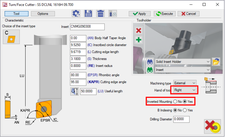
When the tool is mounted on a tool support, it will automatically rotate 180 degrees around its Z-axis. This results in the Z-axis and X-axis being oriented in opposite directions.
Difference between right and left insert holder
In the both cases the system of axis 0 is in the opposite corner of the insert holder.
The Z axis is opposite to the insert.
The X axis is opposite to the “normal” direction of cutting
|
Left insert holder |
|
|
Right insert holder |
|
Key points
-
System of axis 0 is the mounted point on the turret or on tool holder. The system of axis 0 is in accordance with the system axis of tool holder. The Z axis is on the axis of insert holder. The X axis is opposite to the normal direction of machining.
-
If the tool is mounted on tool support on the machine, the Z axis of system of axis 0 is inverted and the X axis is matching with the tool support axes.
-
The origin of system of axis 1 is the point where the center of insert will be mounted. The Z of the system is the normal of the face where the insert is mounted. The X axis must be the most possible oriented in the same direction of the Z axis of the system of axis 0.
|
▶️ Watch a video about Turn insert holder:
|