
Introduction
This video will show how to create the insert of a tool for thread machining.
|
▶️ Watch a video at the bottom of page: Click here |
|
The creation process for tools, symbols, machine, etc. has become more fluid with the interactive system of axes.
|
▶️ Watch a video on the creation process. 
|
General rule for positioning System of Axis
Step 1:
|
|
Define the Z axis normal to surface. |
Step 2:
|
|
Rotate X axis pointing towards the body of the toolholder. |
Step 3:
|
|
Place the system of axis. |
There are three types of cases.
|
1. |
|
Holder with a protruding cylinder (symmetrical). |
|
2. |
|
Using Z direction of insert face and positioning origin. |
|
3. |
|
Using inscribed wireframe circle from insert to position system of axis. |
Creation of turn tool holder
|
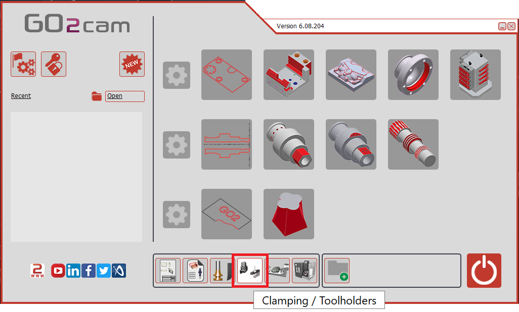
Select the “Clamping / Toolholders” module in the Homepage.
|
|
|
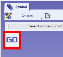
Click the GO button |
|
|
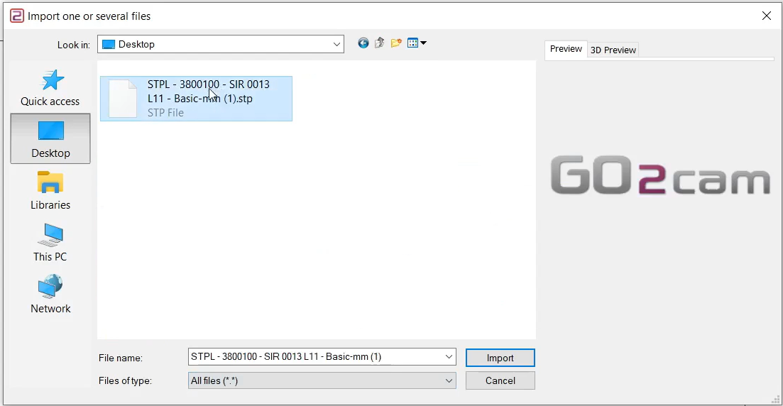
Select the file to import |
|
|
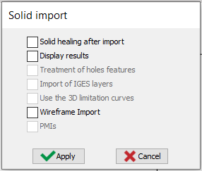
Select the import option to be applied to the solid. Click “Apply”
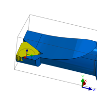
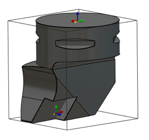
The axis system can also be imported from solid CAD files by activating the Wireframe Import option. This feature is particularly useful for creating holders by importing STEP files from databases such as Sandvik or Iscar. It allows the recovery of the axis systems for positioning inserts, as illustrated for the turning tool in the image on the right. |
|
|
|
|
Click on the tab “Creation” then “Tool Holders” menu |
|
|
Click the command to create system of axis |
|
|
Select the tool to define the position of system of axis |
|
|
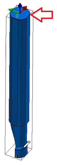
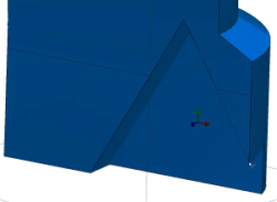
Select the surface/point that will be the point origin of system of axis. The system of axis referenced 0 define the point that will mounted on the previous element. The previous element can be a tool support or another tool holder component. There are two methods to add the system of axis: Select the top surface of the tool as shown with the red arrow. Make sure to zoom in when selecting the face. |
|
|
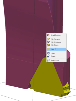
Hide the toolholder’s body.
|
|
|
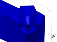
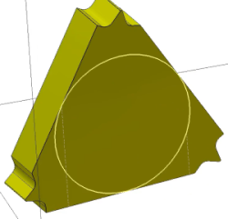
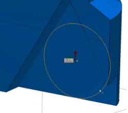
Use circle creation to draw a 3 point circle wireframe on the inside face (the face touching the toolholder body) of the insert. |
|
|
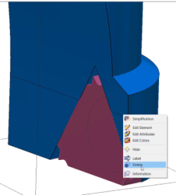
Unhide the toolholder’s body and delete the insert. |
|
|
Select the command to create system of axis again |
|
|
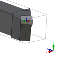
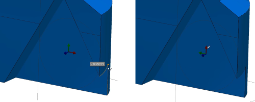
Use the command 'Selection of an insertion axis' to select the inside face to place the z axis normal to it. |
|
|
Use the 'Selection of a reference axis' to orient the X axis as shown. |
|
|
Using CTRL+Shift key to place the system of axis in the middle of the drawn circle via the 'Selection of the origin' command. |
|
|
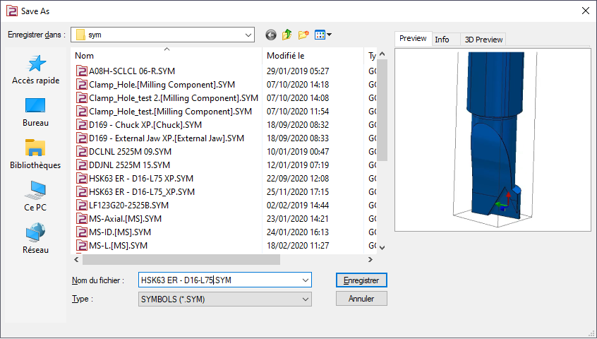
Save the file in the user’s symbol folder for use in GO2cam. |
|
|
▶️ Watch a video about the creation of insert holder for threading tool:
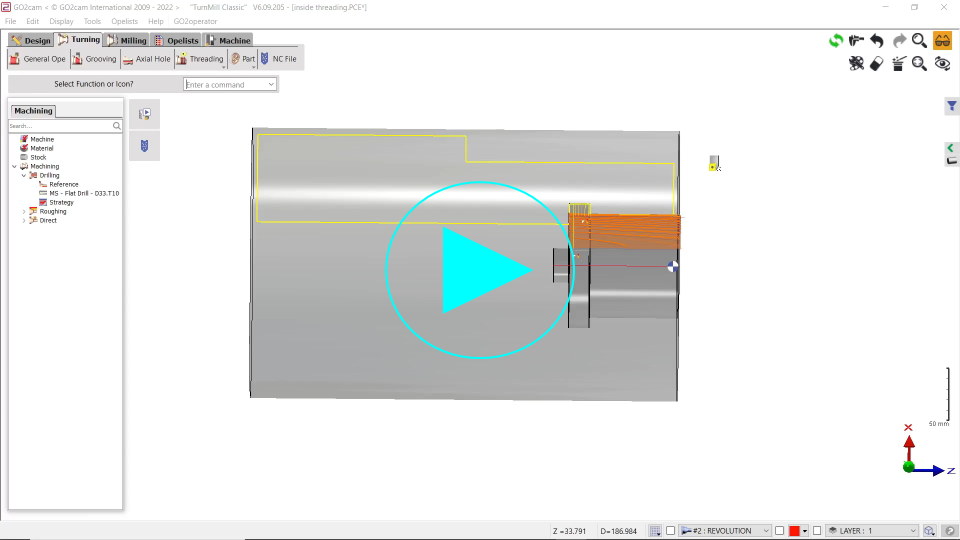
|