
Introduction
This page explains how to create a vise with two symmetrical mobile jaws for a Milling machine.
|
▶️ Watch a video at the bottom of page: Click here |
|
The creation process for tools, symbols, machine, etc. has become more fluid with the interactive system of axes.
|
▶️ Watch a video on the creation process. 
|
Creation of Symmetrical Vice
|
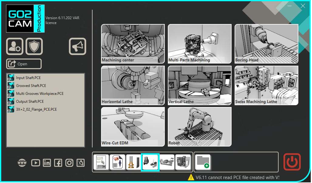
Select the “Clamping / Toolholders” module in the Homepage. |
|
|
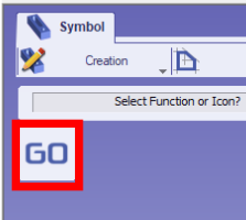
Click the GO button |
|
|
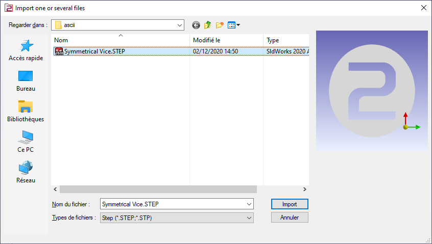
Select the file to import |
|
|
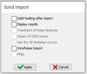
Select the import option to be applied to the solid. Click “Apply” |
|
|
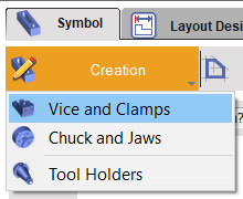
Click on the tab “Creation” then “Vice and Clamps” menu |
|
|
Click the command to create system of axis |
|
|
Select the tool to define the position of system of axis |
|
|
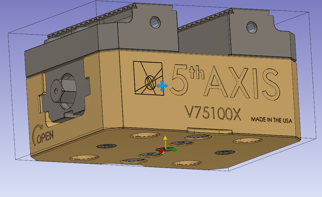
Define the system of axis 0.
Do a click on the bottom face and validate.
The system of axis will match with the system of axis, of work assembly support, where the vise will be mounted.
|
|
|
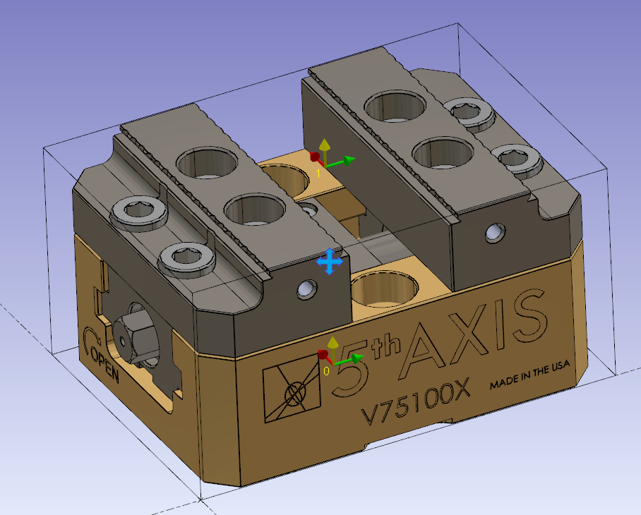
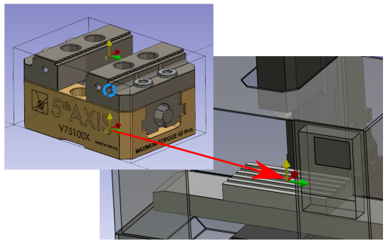
Do the same command to create the system of axis 1.
The system of axis 1 will be the point you can drive when you set the position of the vice on the part. For symmetrical vice, it should be centered between the two jaws.
Note: For the height of the axis, use the Z Altitude and pick the topmost part of the vice. |
|
|
Click on the component vectors tool. |

|
|
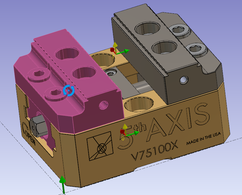
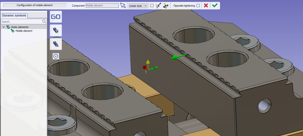
Select the first jaw as mobile element. |
|
|
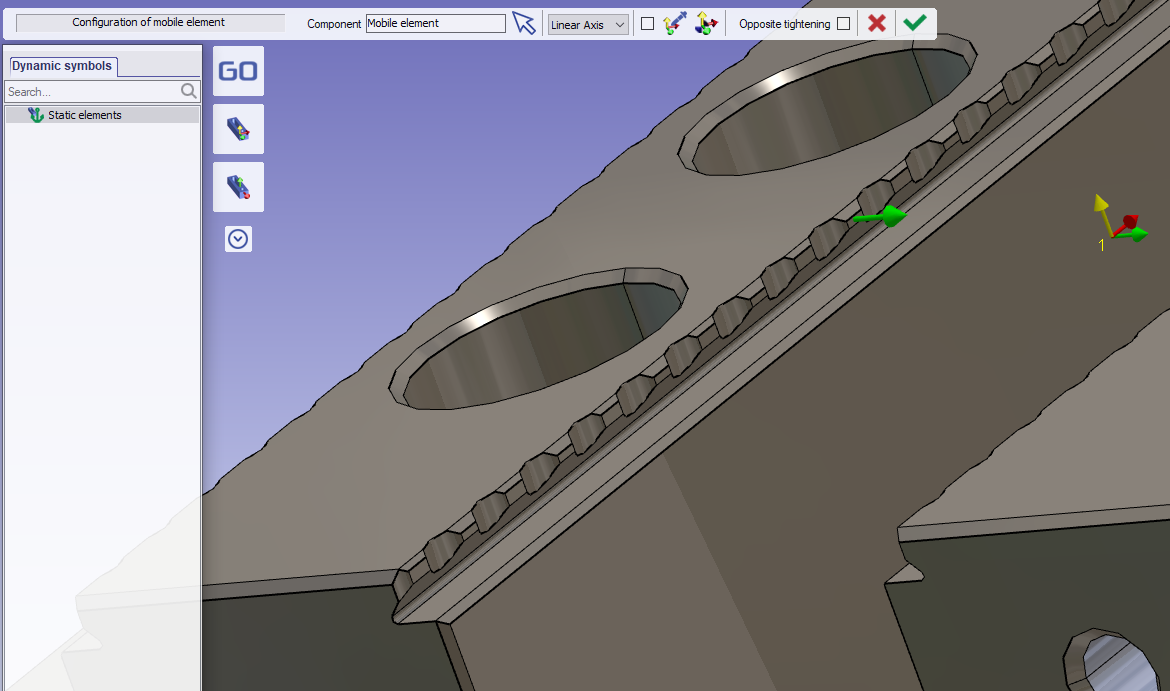
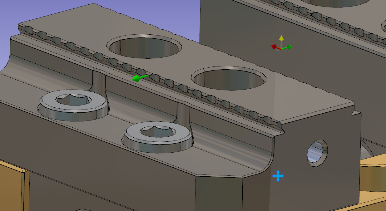
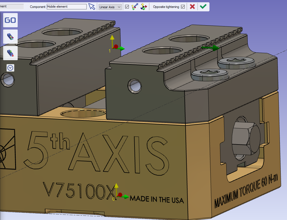
Then click the tool to create direction of movement. |
|
|
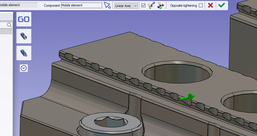
Click the face of mobile jaw. |
|
|
Validate the mobile element creation. |
|
|
Do the same operation for the second jaw. |
|
|
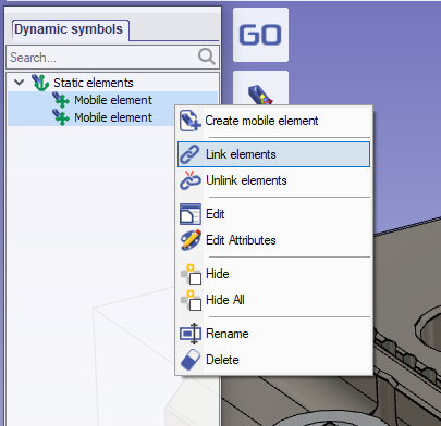
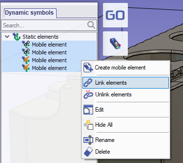
To synchronize the movement of two jaws, select both on the left tree. Do a Right-click to display the popup menu then “Link elements”.
The linked elements will move with the same distance in the direction defined on it. |
|
|
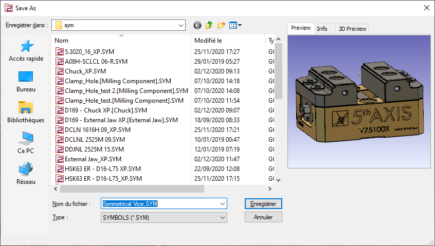
Save the file in the user’s symbol folder for use in GO2cam. |
|
Complementary information
This kind of vice gives the possibility to invert the jaw and have another tightening position.
It is possible to configure it in the same symbol. To do this, follow the next steps.
|
Open the previous vice |
|
|
Add mobile element without solid.
|
|
|
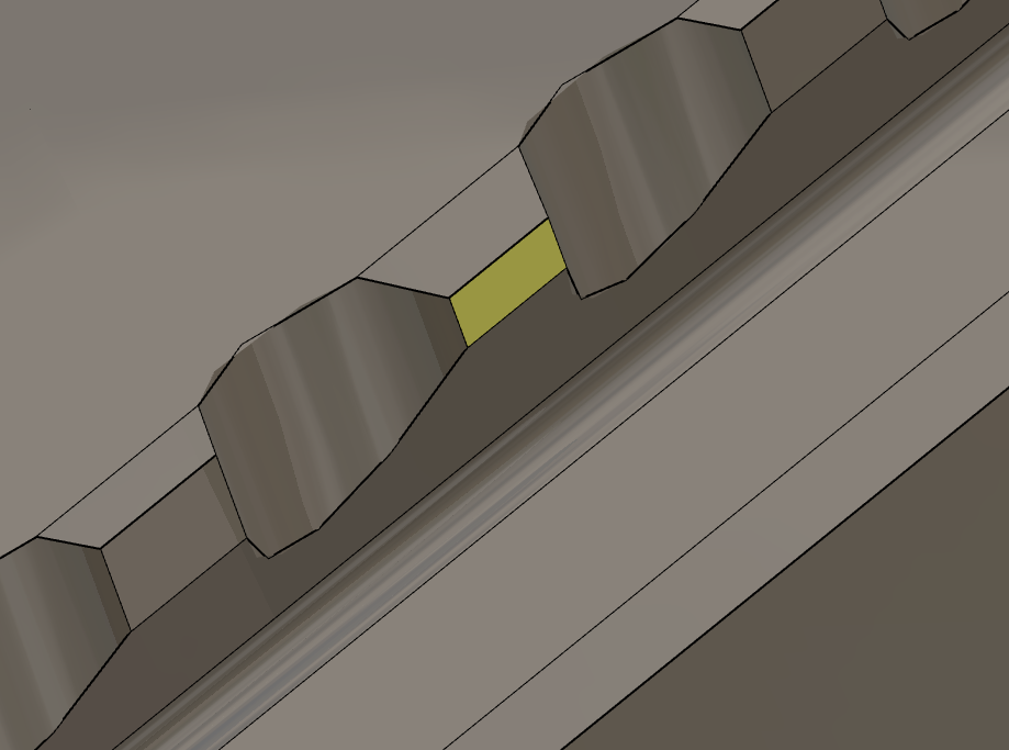
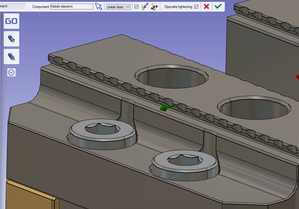
Invert the direction of the vector to set the movement opposite to the selected face. |
|
|
Check the “Opposite tightening” option to invert the display of the vector.
The color of the vector changes and the display is inverted.
Then validate the new mobile element. |
|
|
Do the same for the other side. |
|
|
Link the four mobile elements together. |
|
|
Save your symbol |
|
|
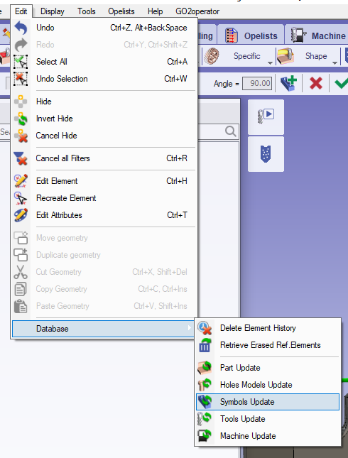
Important: If the symbol is to be used in a project that already employs its first version, ensure that the symbol database is updated. |
|
Key points
-
The system of axis 0 will be mounted on the work assembly support of the machine.
-
The system of axis 1 will be used to position the vise on the stock.
-
It will have two mobile elements.
-
The mobile elements must be linked to move together.
Multiple axis systems can be defined to position the vise on the stock. To do so, add additional axis systems.
|
|
▶️ Watch a video about Symmetrical vise:
|