
Introduction
This page explains how to create a vice with one mobile jaw for a mill machine.
|
▶️ Watch a video at the bottom of page: Click here |
|
The creation process for tools, symbols, machine, etc. has become more fluid with the interactive system of axes.
|
▶️ Watch a video on the process creation. 
|
Creation of vice
|
Select the “Clamping / Toolholders” module in the Homepage. |
|
|
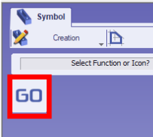
Click the GO button |
|
|
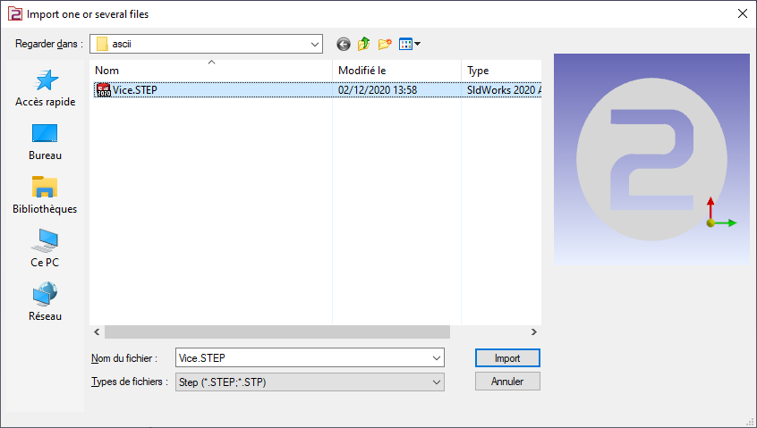
Select the file to import |
|
|
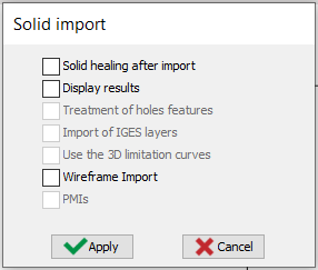
Select the import option to be applied to the solid. Click “Apply” |
|
|
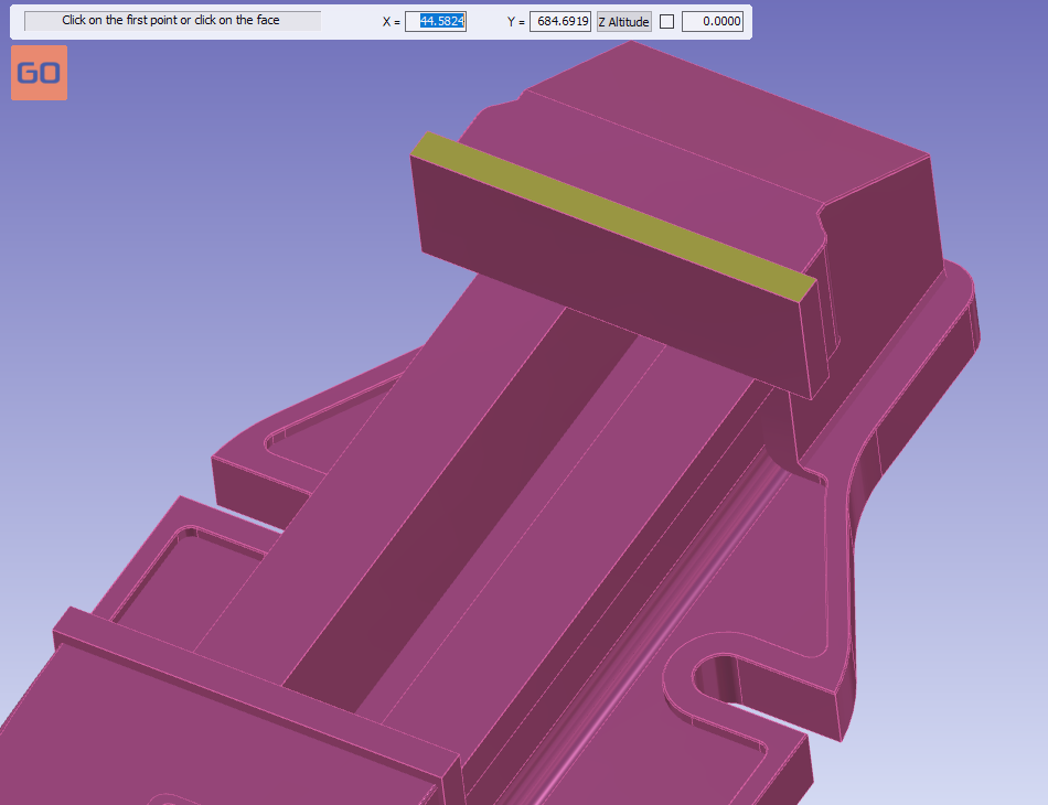
Click the plane face to orientate the vice. The clicking face will have Z axis as normal vector. |
|
|
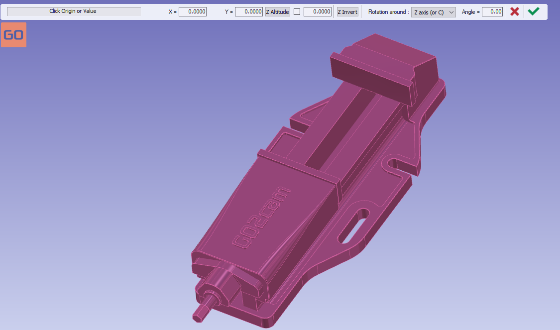
The origin can be directly validated without anymore action. |
|
|
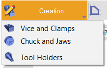
Click on the tab “Creation” then “vice and Clamps” menu |
|
|
Click the command to create system of axis |
|
|
Select the tool to define the position of system of axis |
|
|
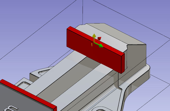
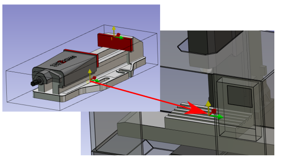
Define the system of axis 0.
The system of axis will match with the system of axis, of work assembly support, where the vice will be mounted.
|
|
|
Do the same command to create the system of axis 1.
The system of axis 1 will be the point you can drive when you set the position of the vice on the part. |
|
|
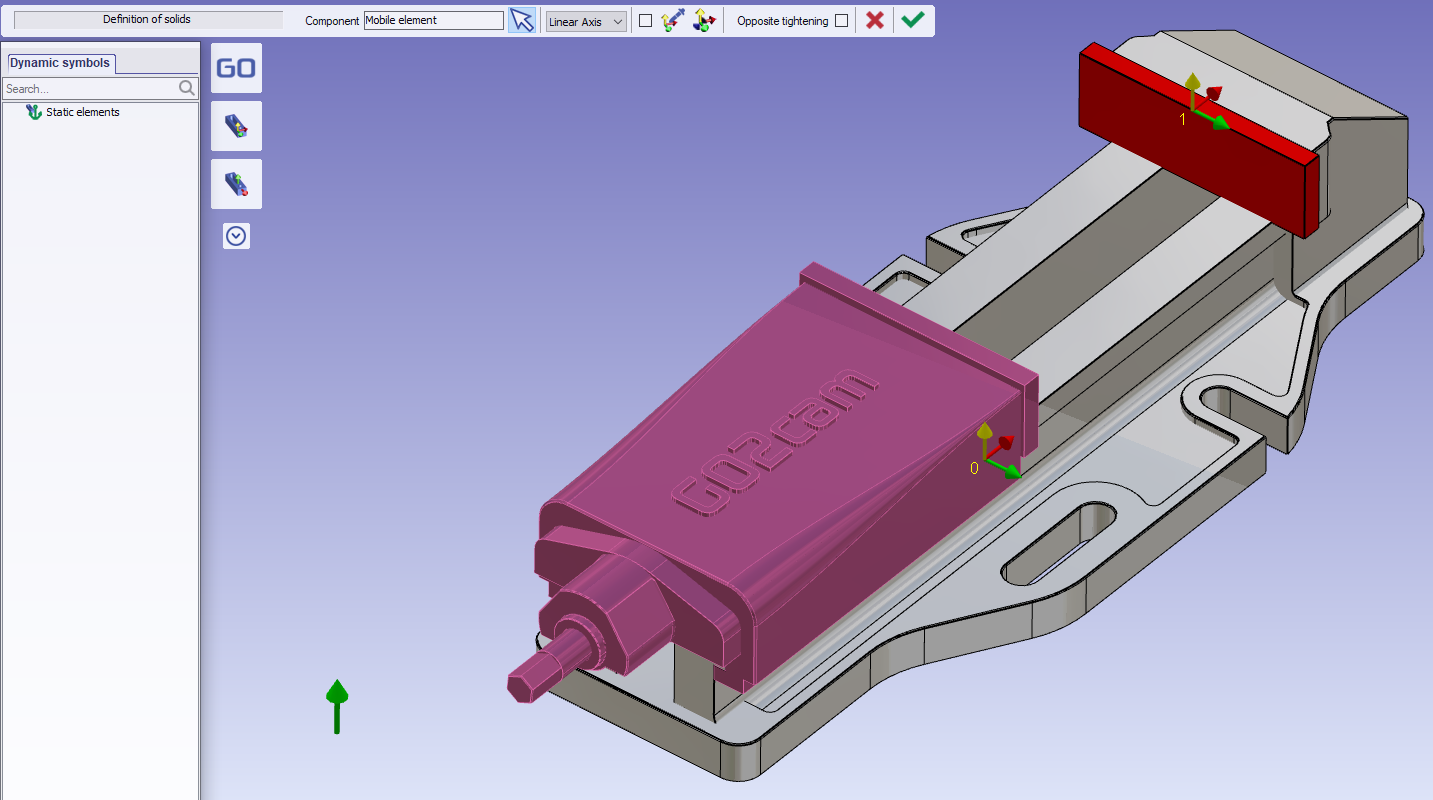
Click on the component vectors tool. |

|
|
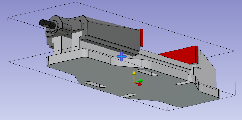
Please select the mobile element. All the geometry not selected in mobile element will be consider as fixed element. |
|
|
The click the tool to create direction of movement |
|
|
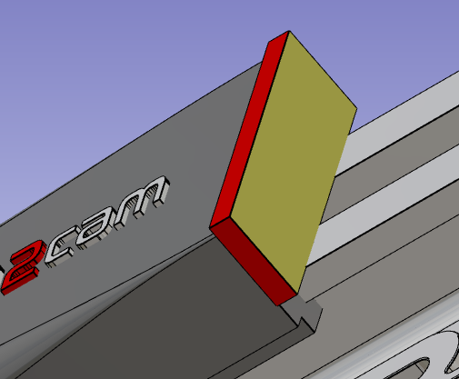
Click the face of mobile jaw |
|
|
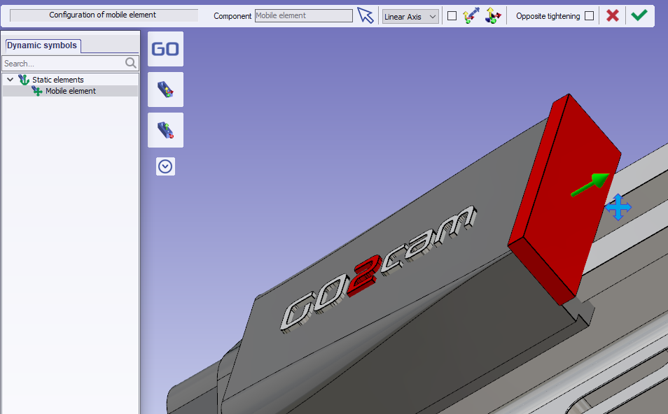
Validate the mobile element creation |
|
|
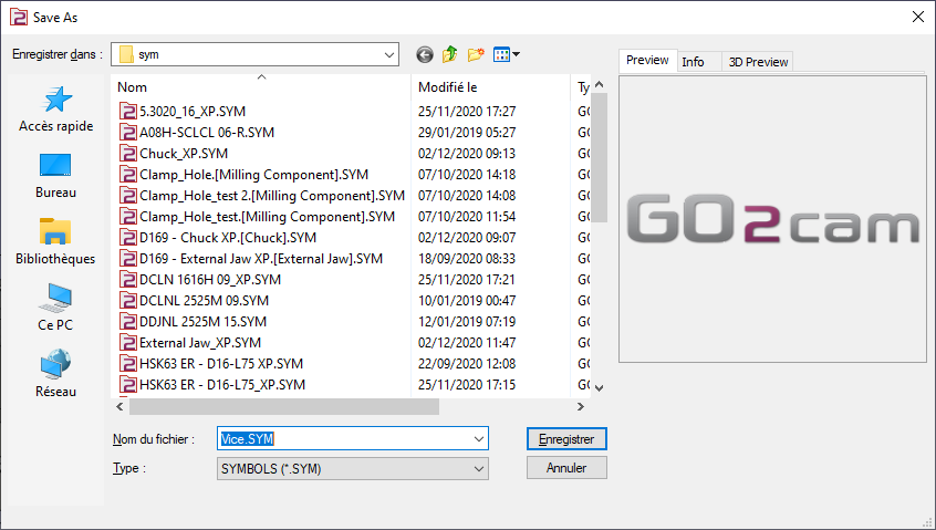
Save the file in the user’s symbol folder for use in GO2cam. |
|
Key points
-
The system of axis 0 will be mounted on the work assembly support of the machine.
-
The system of axis 1 will be used to position the vice on the stock.
Multiple axis systems can be defined to position the vice on the stock. To achieve this, add additional axis systems.
|
▶️ Watch a video about Single vice:
|