
Introduction
This page shows the creation of vectors of components of a vice and you will see how different positioning are made.
|
▶️ Watch a video at the bottom of page: Click here |
|
The creation process for tools, symbols, machine, etc. has become more fluid with the interactive system of axes.
|
▶️ Watch a video on the creation process. 
|
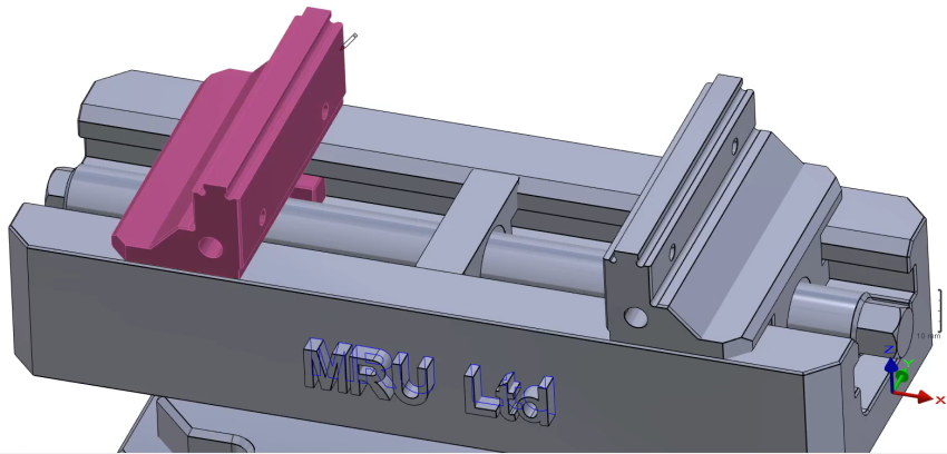
Creation of Vice with Multi-Tightening
|
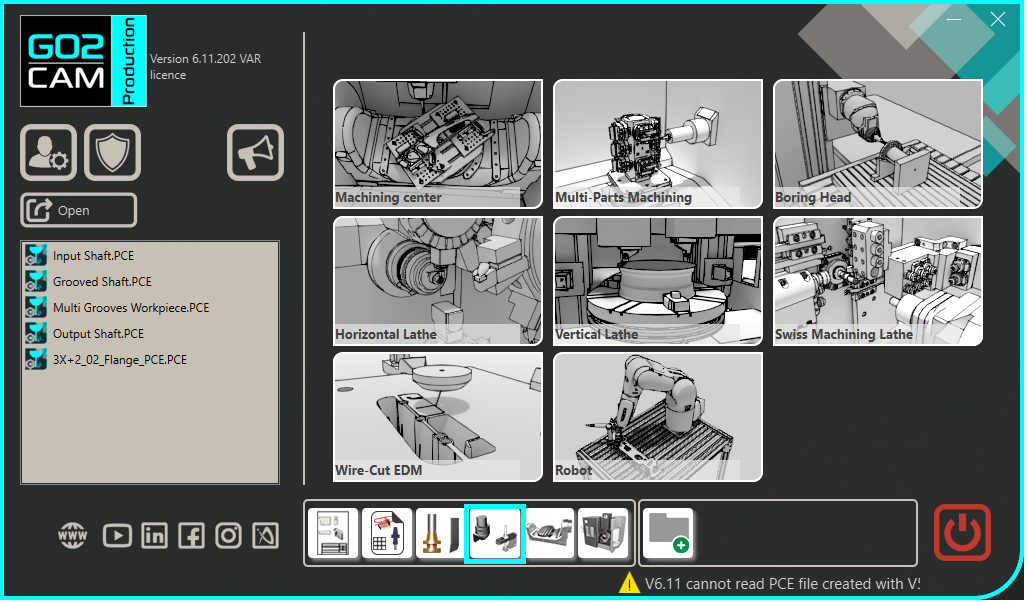
Select the “Clamping / Toolholders” module in the Homepage. |
|
|
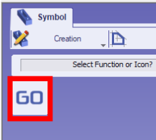
Click the GO button |
|
|
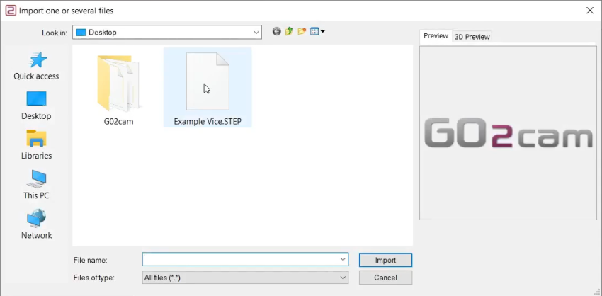
Select the file to import |
|
|
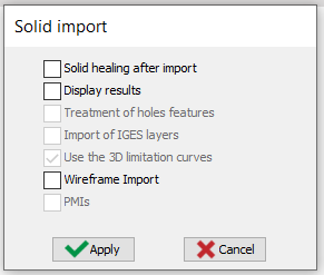
Select the import option to be applied to the solid. Click “Apply” |
|
|
Click on the tab “Creation” then “Vice and Clamps” menu |
|
|
Click the command 'Component Vectors' to create the vectors for the mobile elements. |
|
|
Select the mobile part which will be associated to the vector. |
|
|
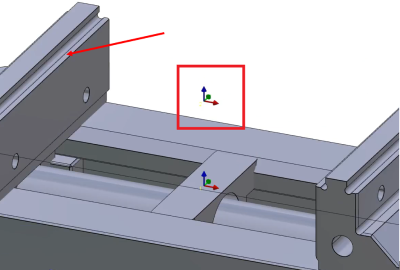
Select the command 'orientate the axis' to define the position of system of axis. |
|
|
And click again on the reference face and then the ‘green tick’ to validate. |
|
|
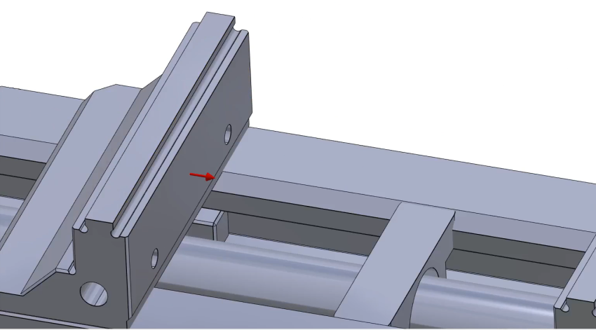
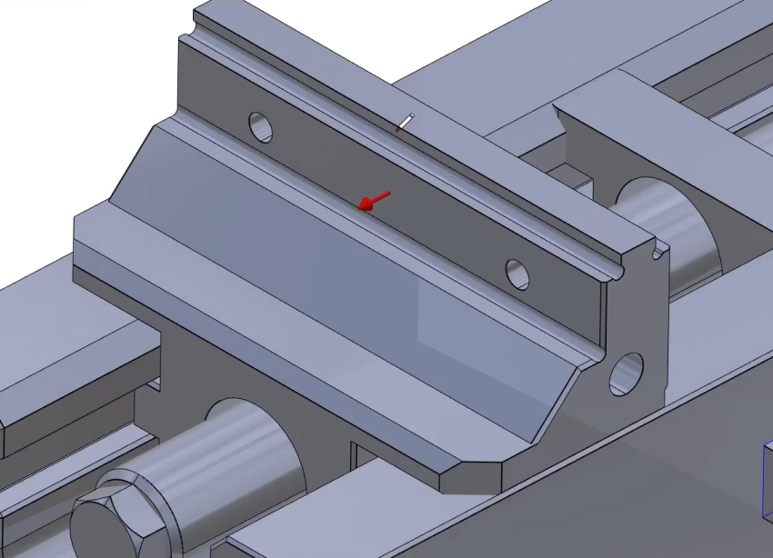
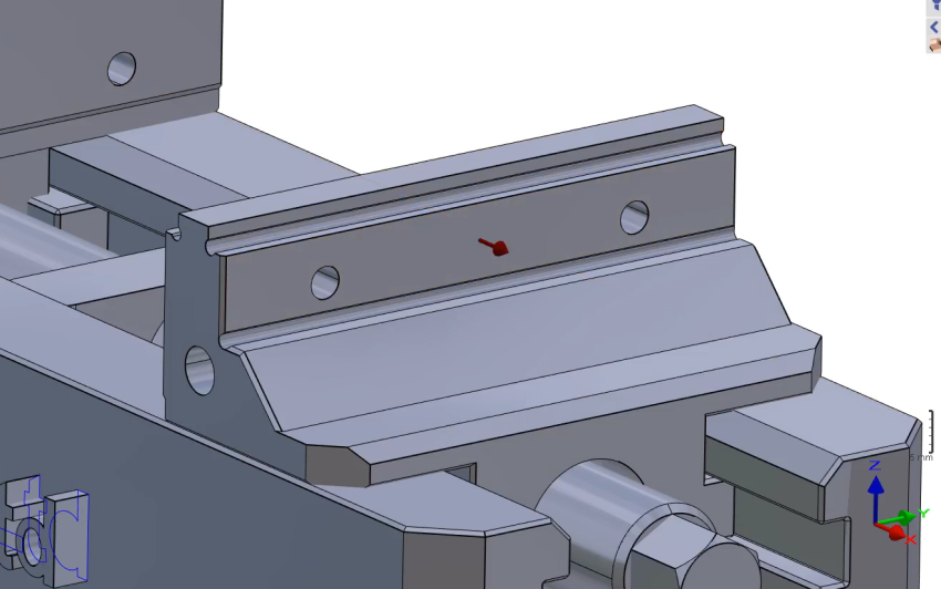
Select the commands 'Component Vectors' then 'orientate the axis' and click on the face of the mobile element to create the vector as shown. |
|
|
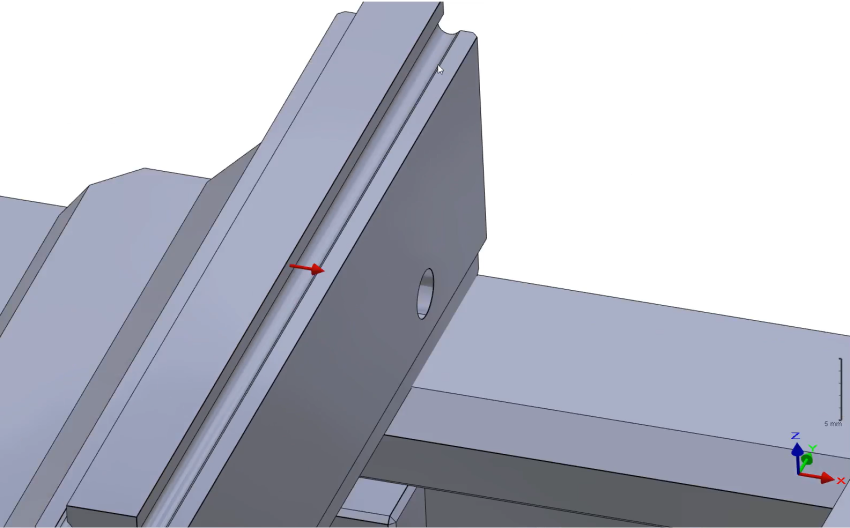
Repeat the same procedure to create a create on the opposite side of the mobile element as shown. |
|
|
Check the box 'Inversion of the vector direction' to invert the vector direction. Since it is the opposite side of the jaw, activate the checkbox for 'Opposite Tightening', then validate with the green tick. |
|
|
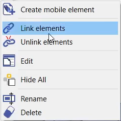
On the dynamic symbols tree, select all three ‘Mobile elements’. Then right-click and select 'Link elements'. |
|
|
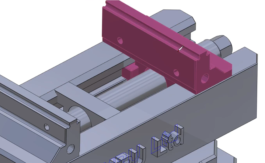
Repeat the process for the second jaw. First, click the command 'Component Vectors' to create system of axis. Then select the mobile element as shown. |
|
|
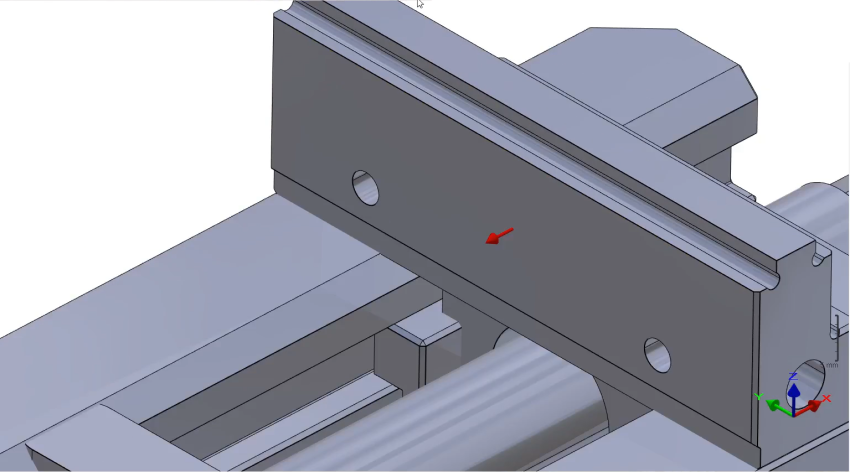
Select 'orientate the axis' and click on the face of the mobile element to create the vector as shown. then validate.
|
|
|
Click on the command 'Component Vectors' and select 'orientate the axis' again then select the face shown to create the vectors. Then validate. |
|
|
Repeat the procedure on the other side of the second jaw. Then link the three newly created elements. |
|
|
Click the command 'Creation of System of Axis'. |
|
|
Select the tool to define the position of system of axis |
|
|
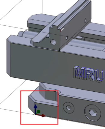
Define the system of axis 0 as shown on the image.
|
|
|
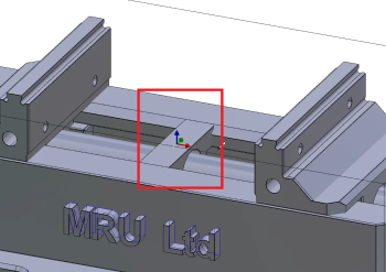
Repeat the same process to define the system of axis 1 as shown on the image. |
|
|
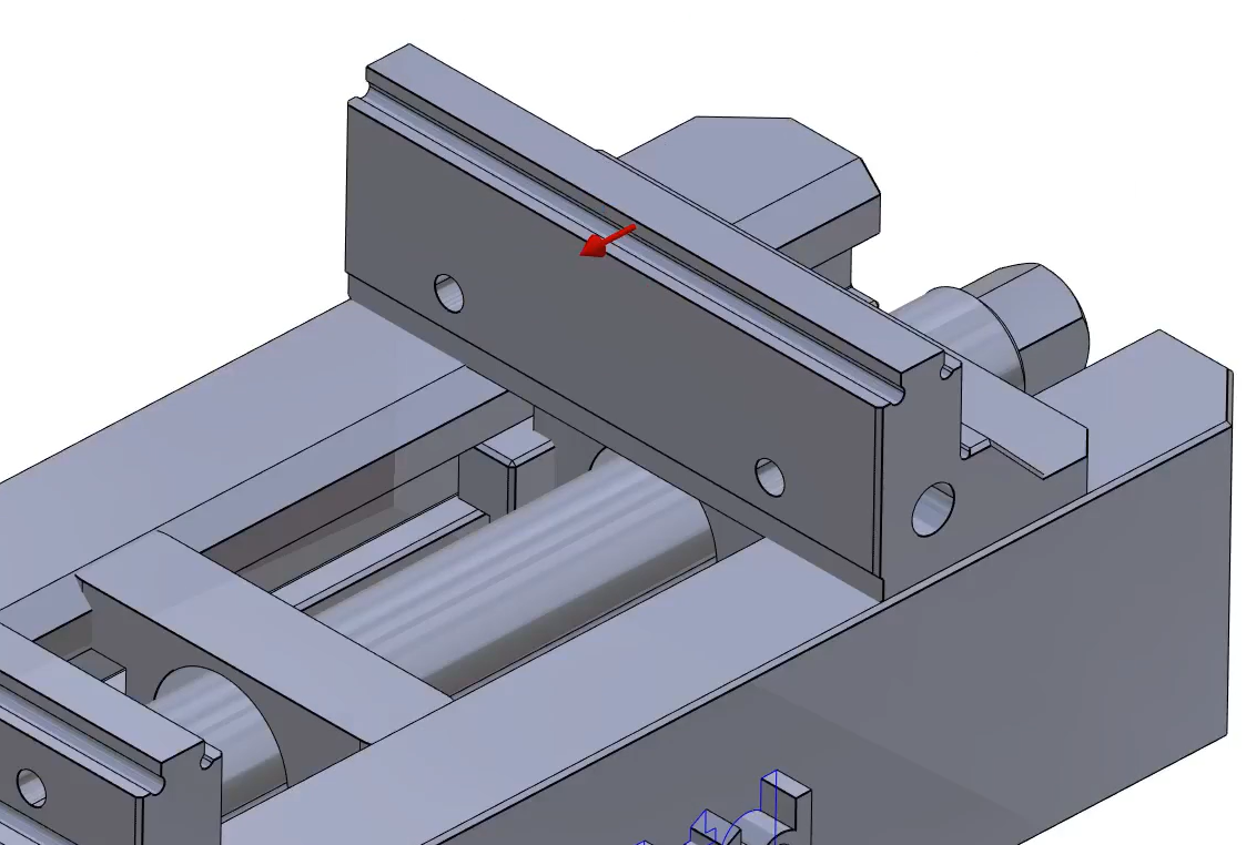
Create the System of axis 2 on the same position as system of axis 1 but at an altitude of 89 (either type-in or click on the face shown by the arrow).
|
|
|
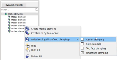
On the dynamic symbols tree, Right-Click on Static elements, go on ‘Aided setting' and check 'Center clamping’ |
|
|
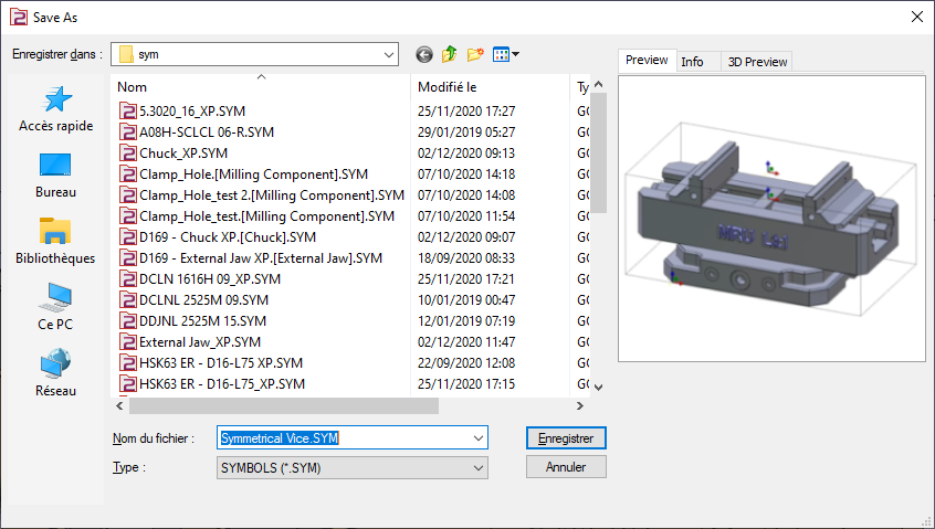
Save the file in the user’s symbol folder for use in GO2cam. |
|
|
▶️ Watch video showing how to create a vise with Multi-tightening and how to use it on a solid.
|