
|
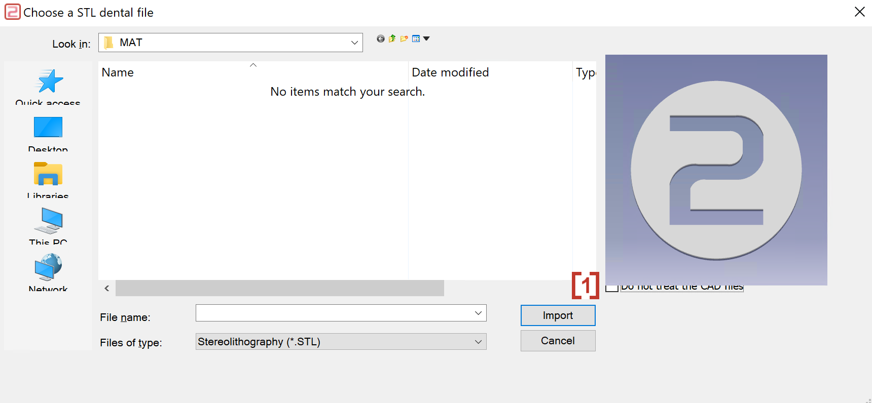
Click the icon to import an STL file.
|

|
|
In the pop-up window, activate 'Do not treat the CAD files' to import CAD files without optimizing spatial attitude. |
|
|
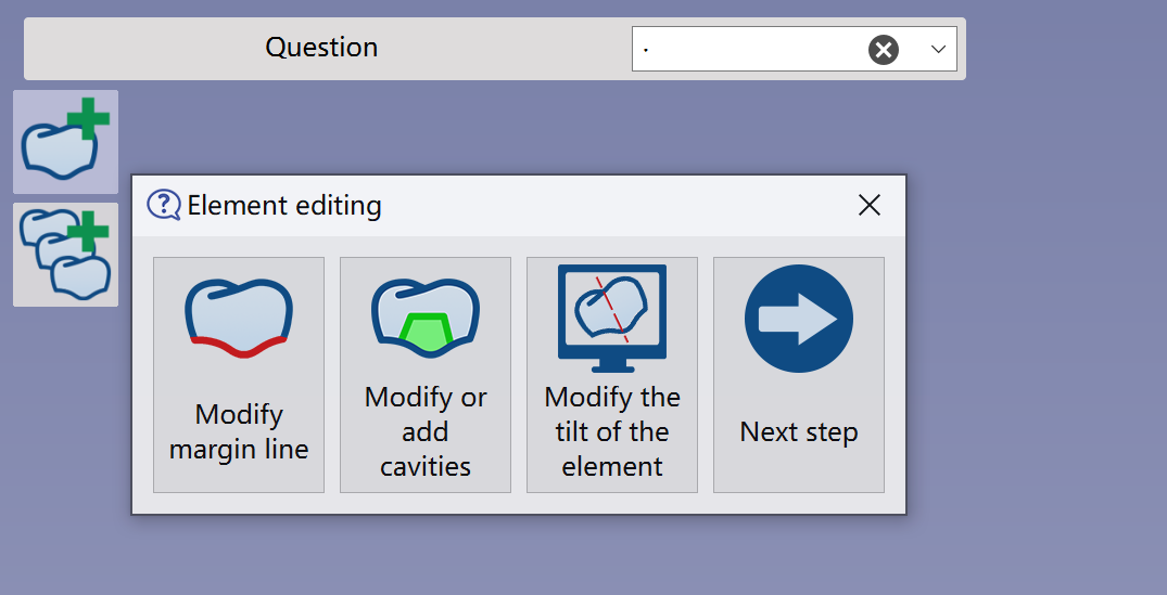
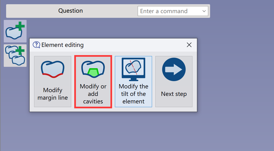
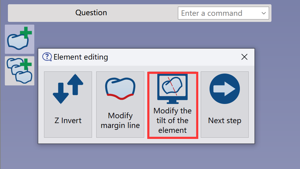
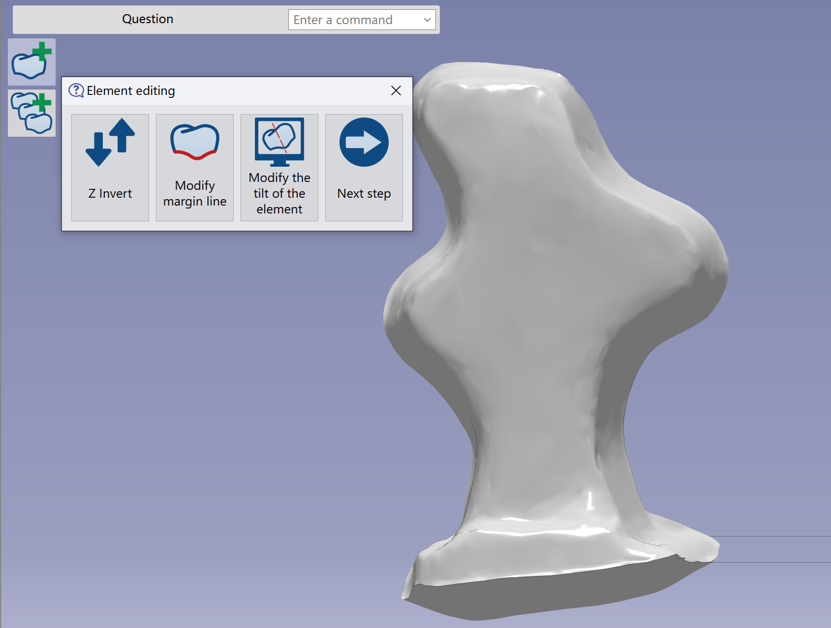
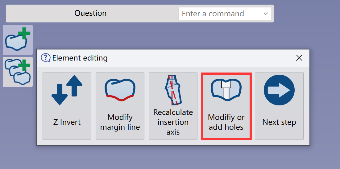
The Element Editing window appears, letting users apply specific functions. |
|
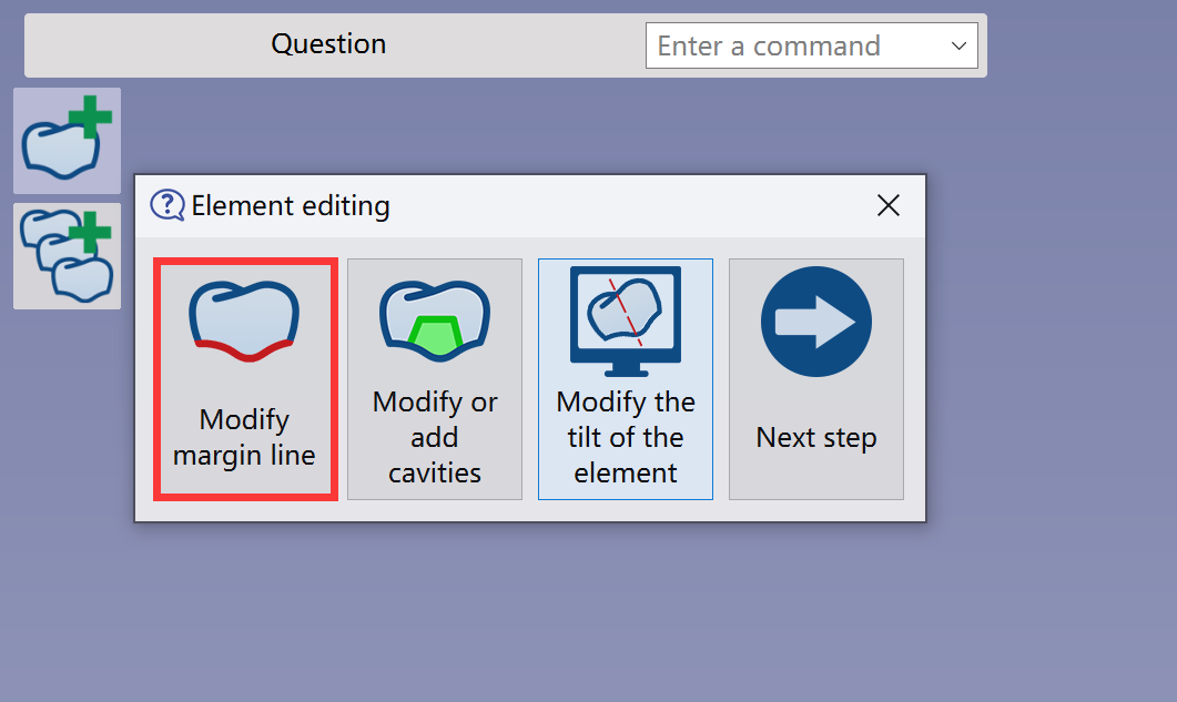
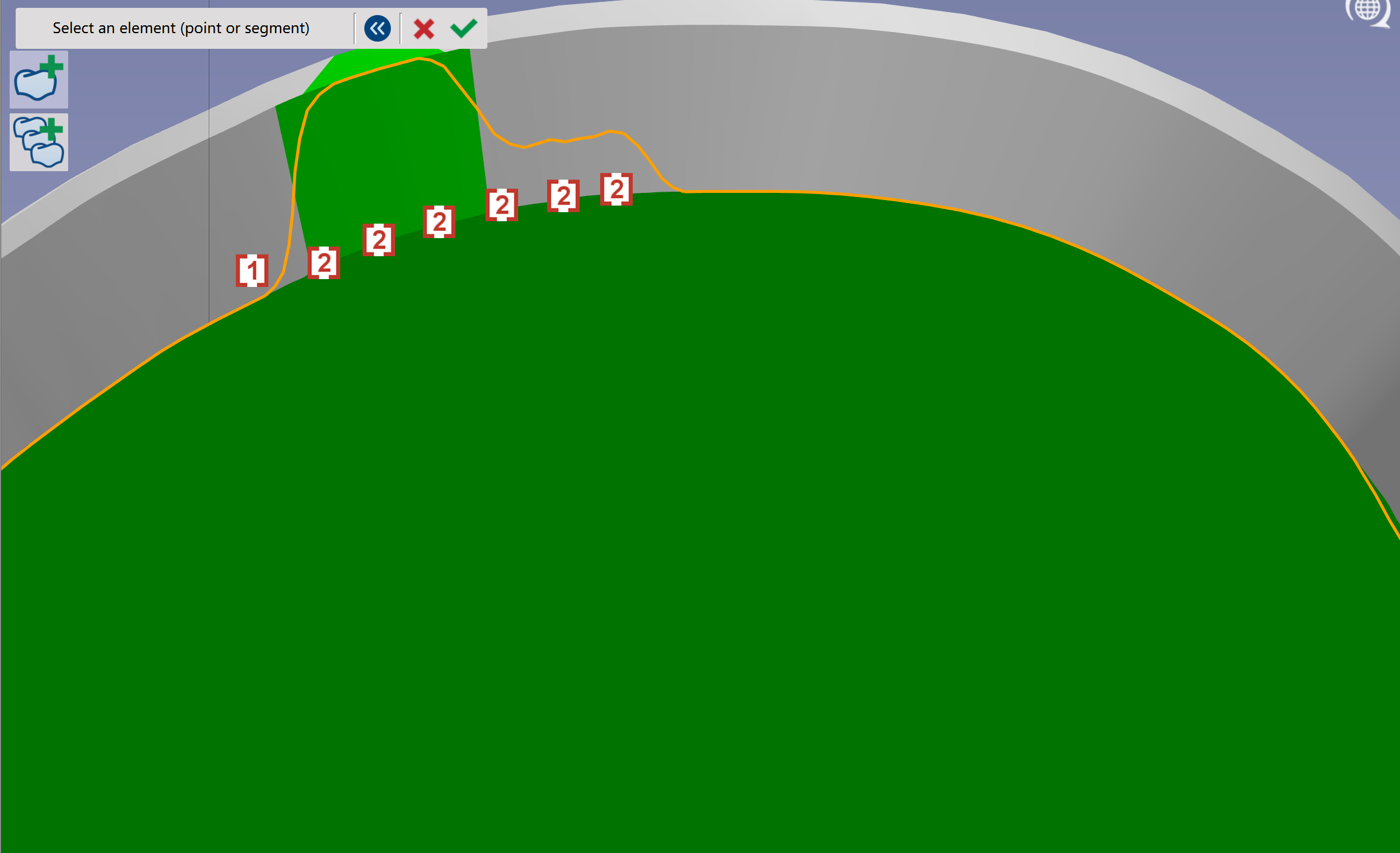
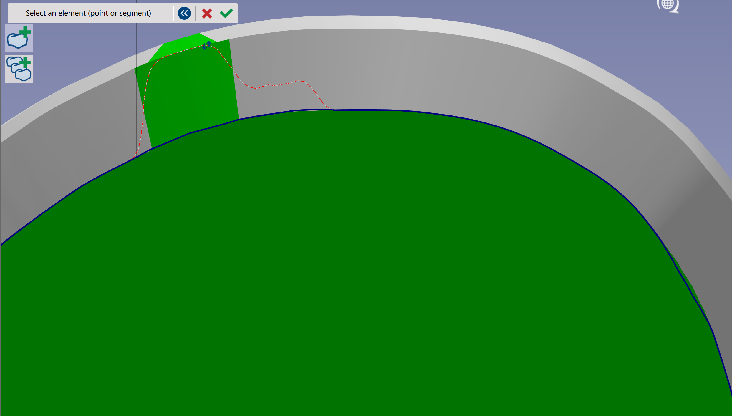
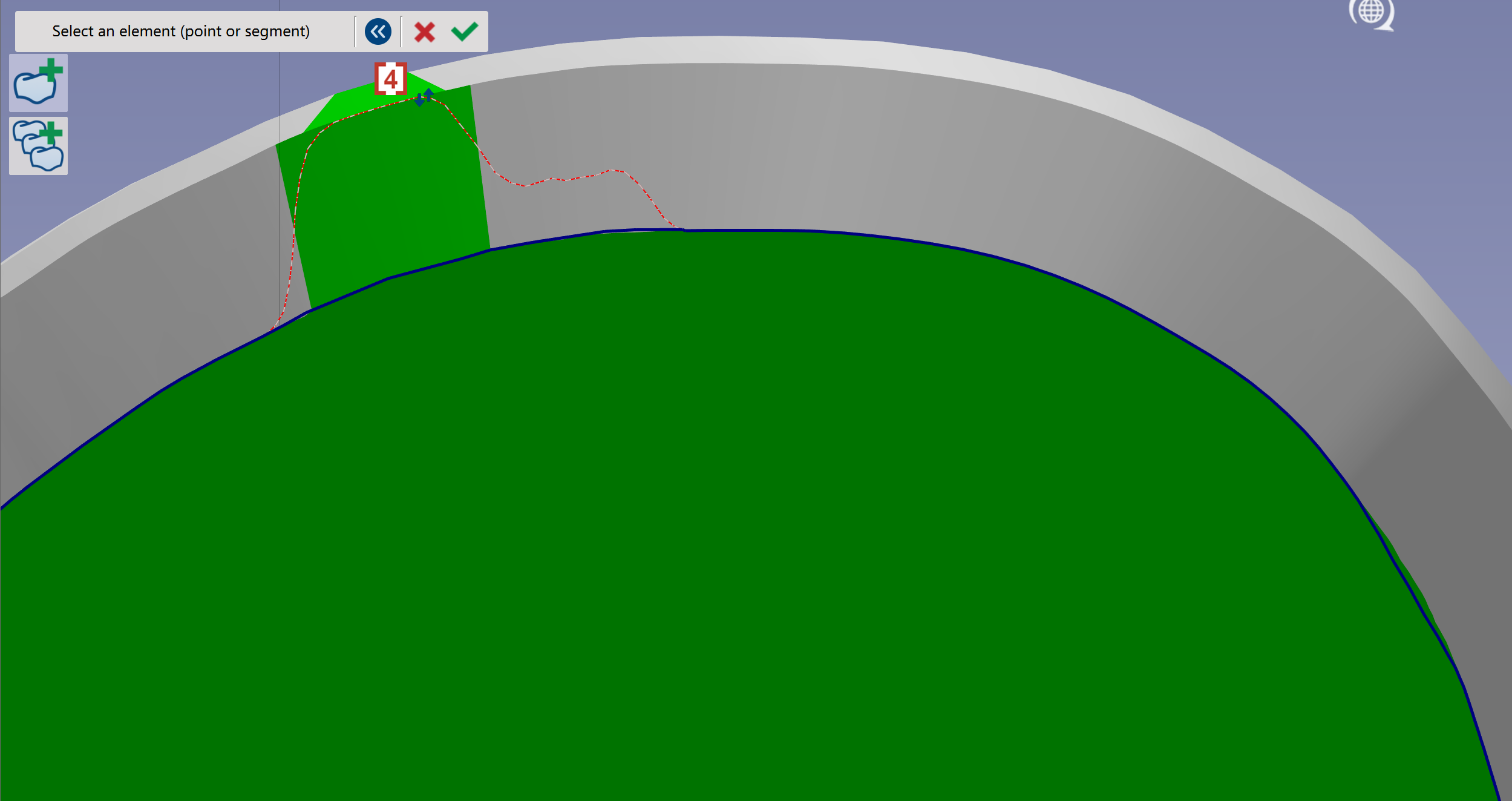
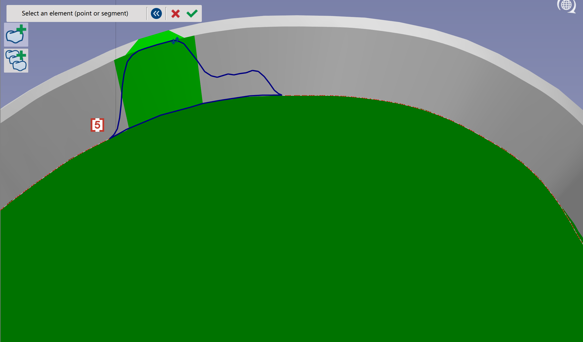
Element Editing
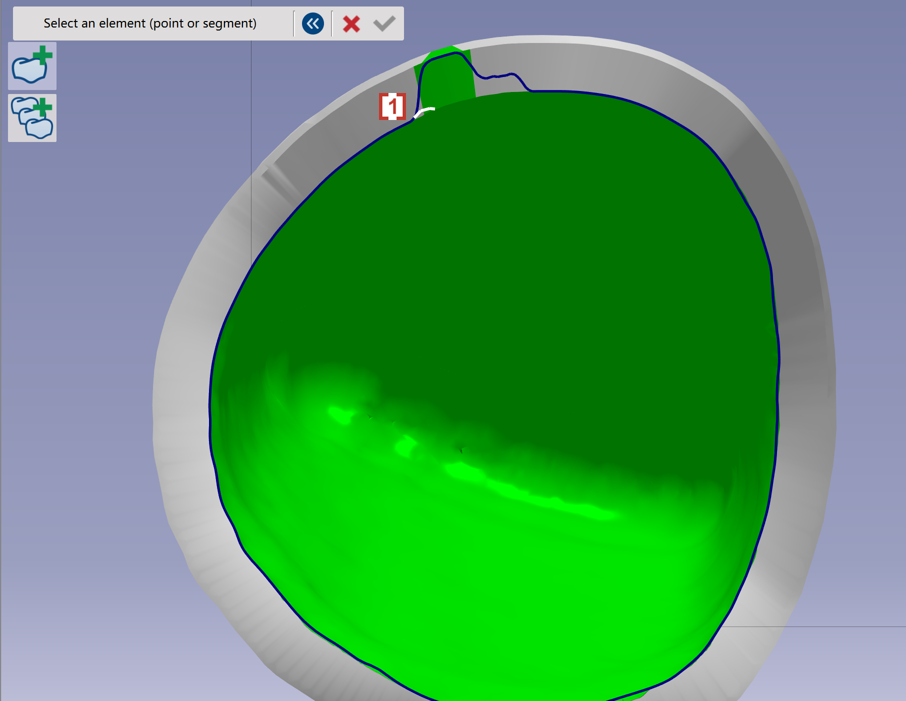
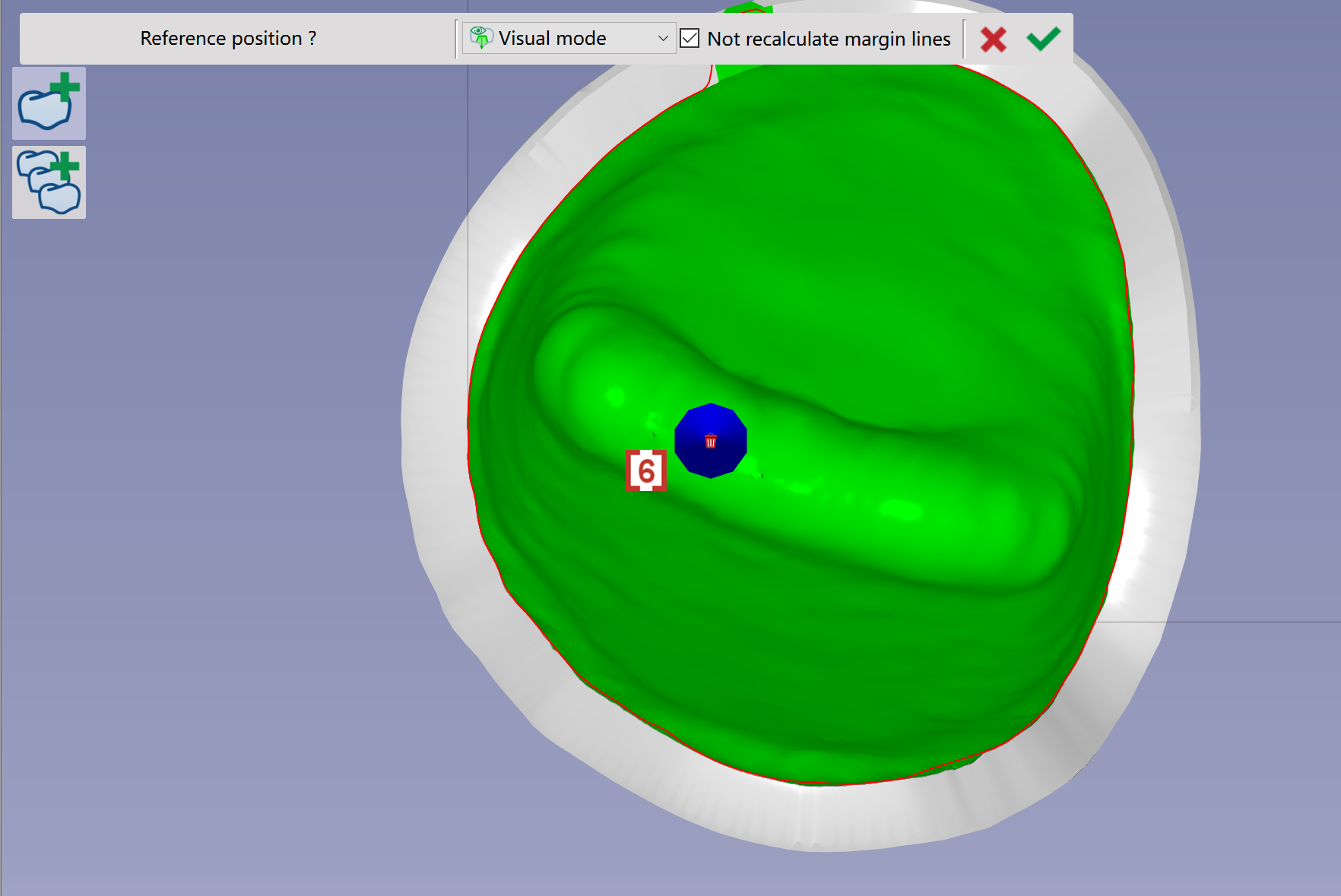
Change margin line
|
|
|
|
|
|
|

|
|
|
|
|
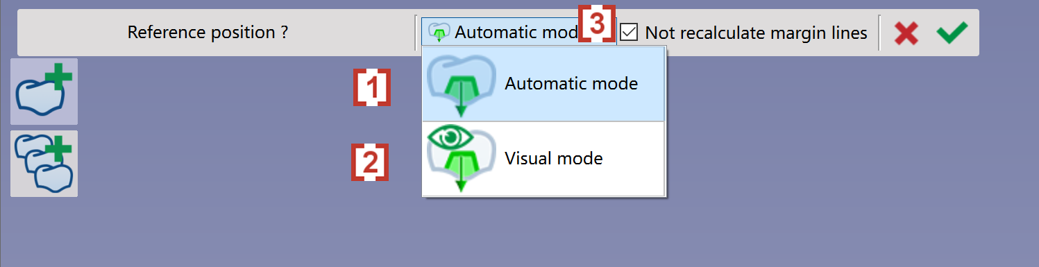
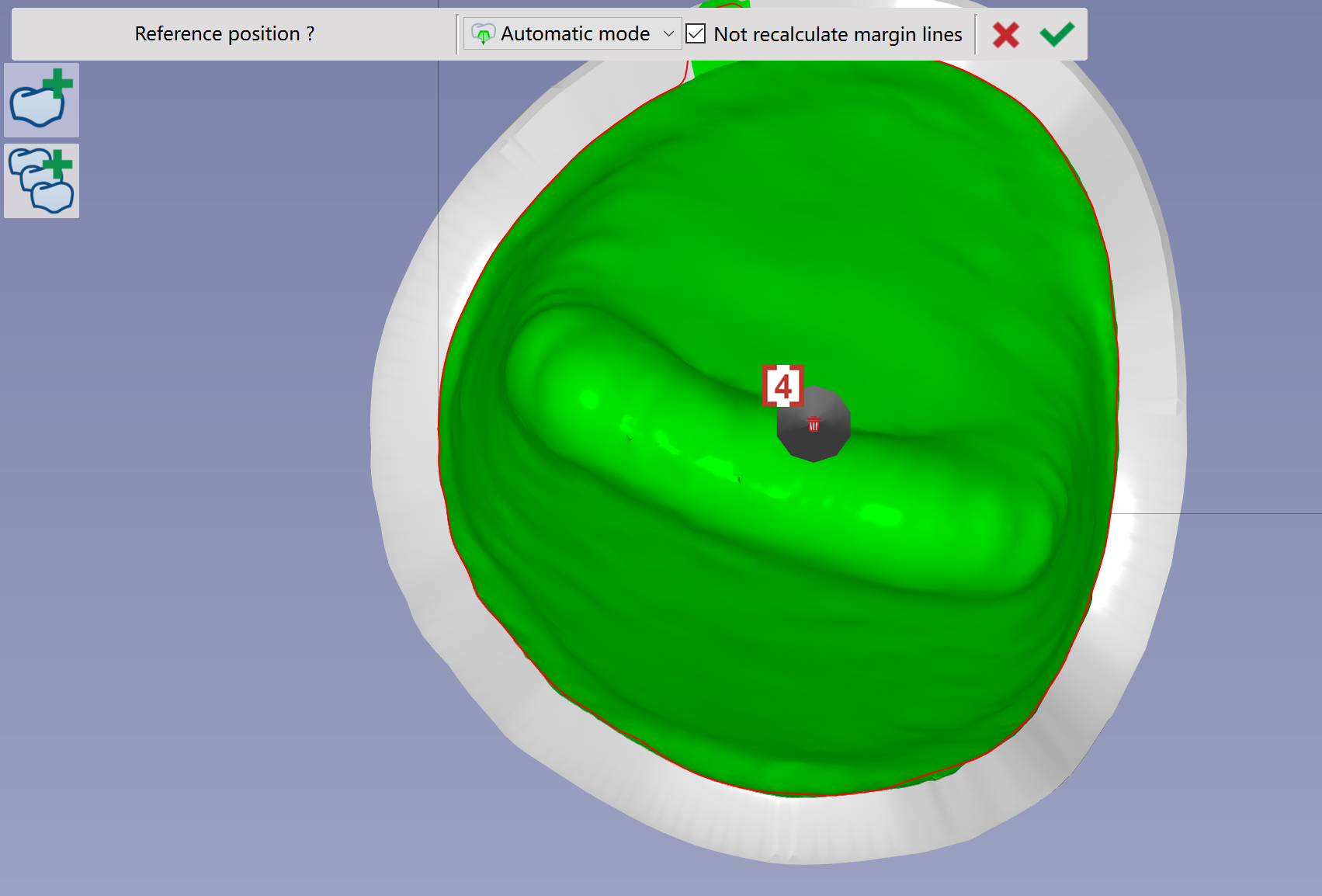
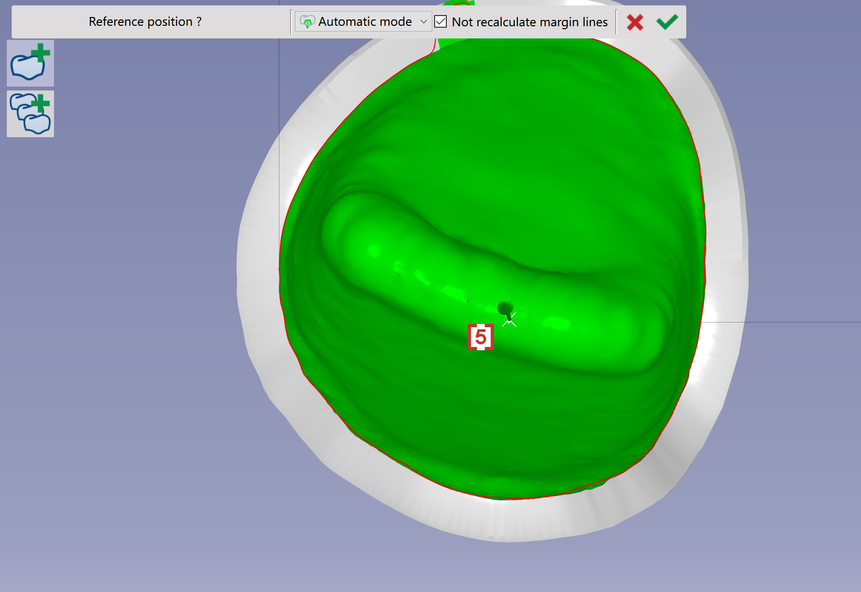
Modify or add cavities
|
|
|
|
|
|
|
|
|
|
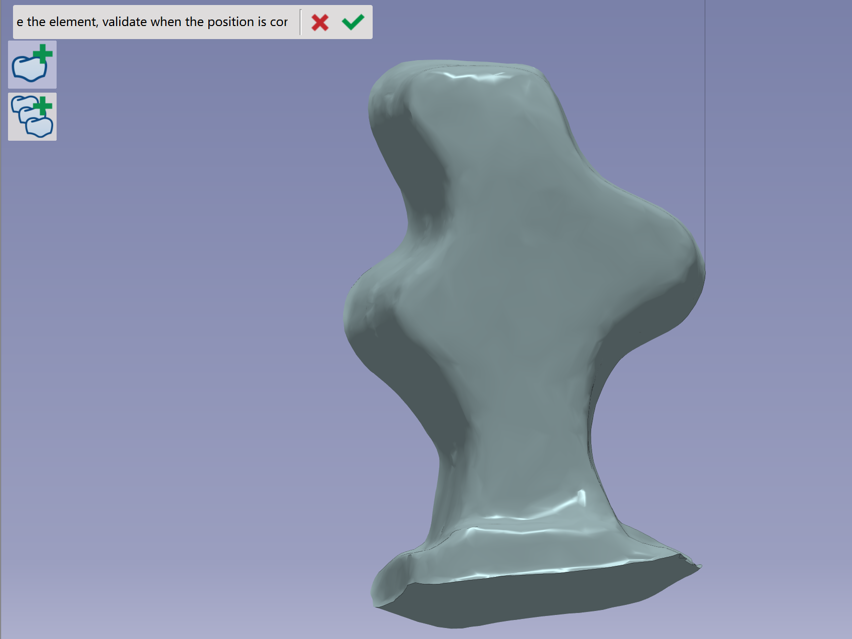
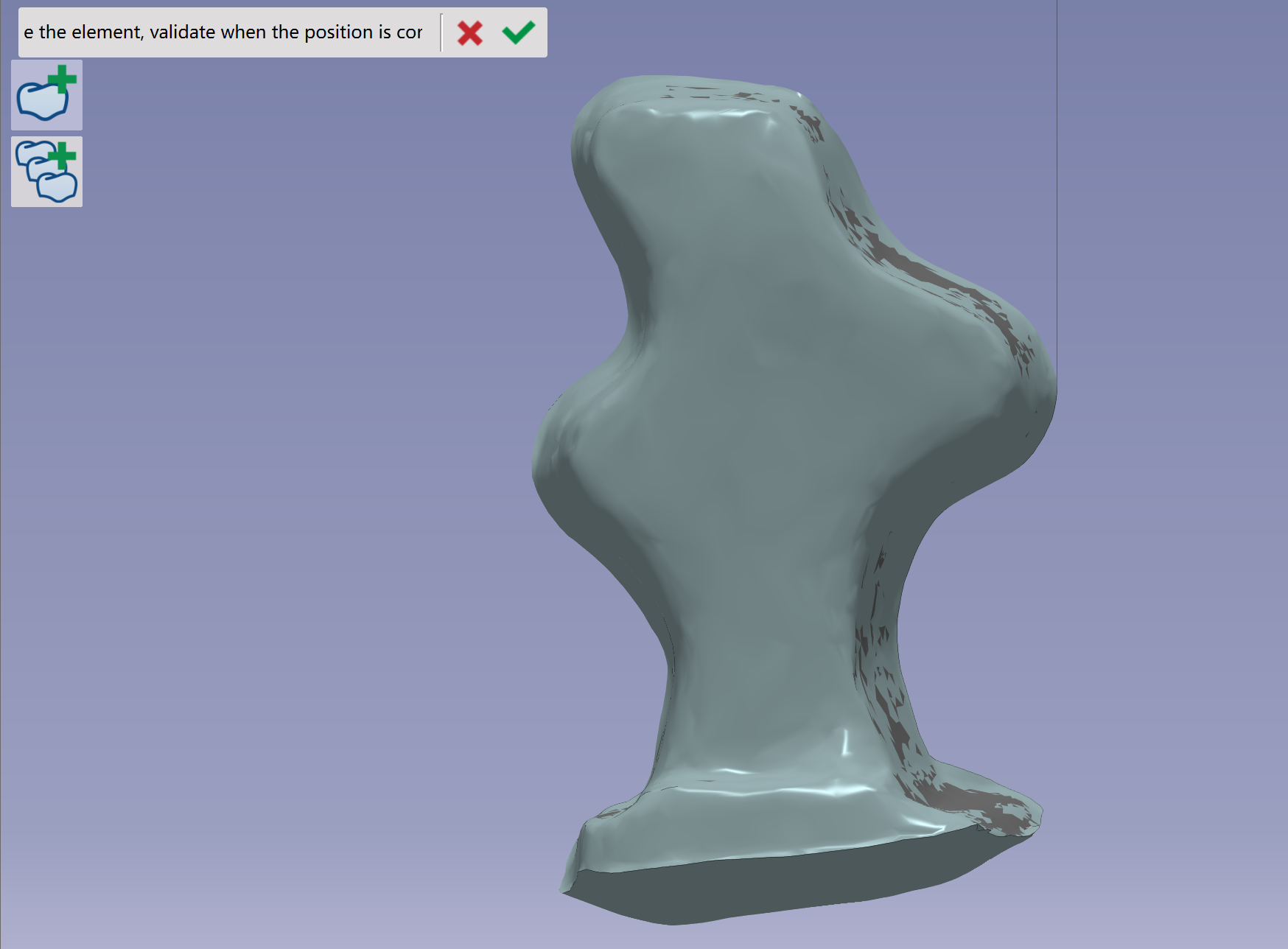
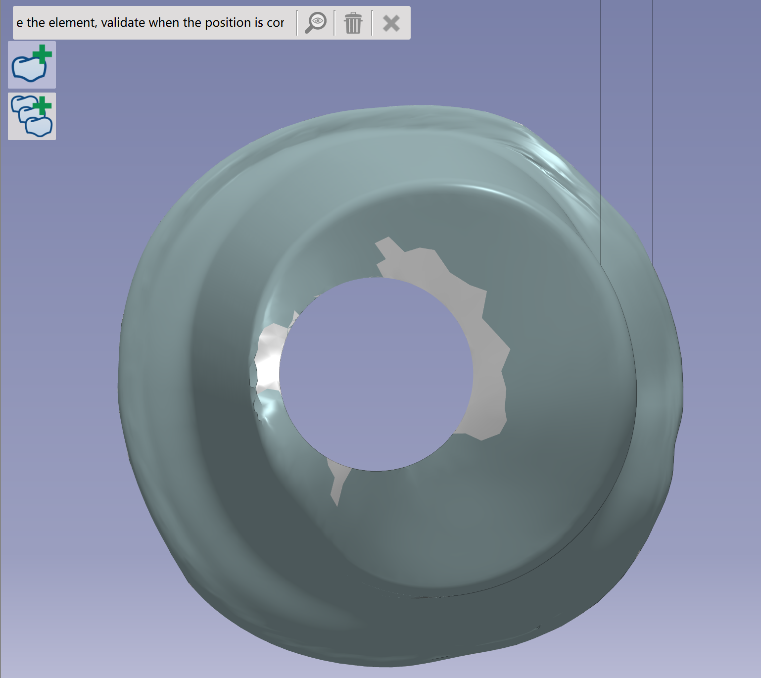
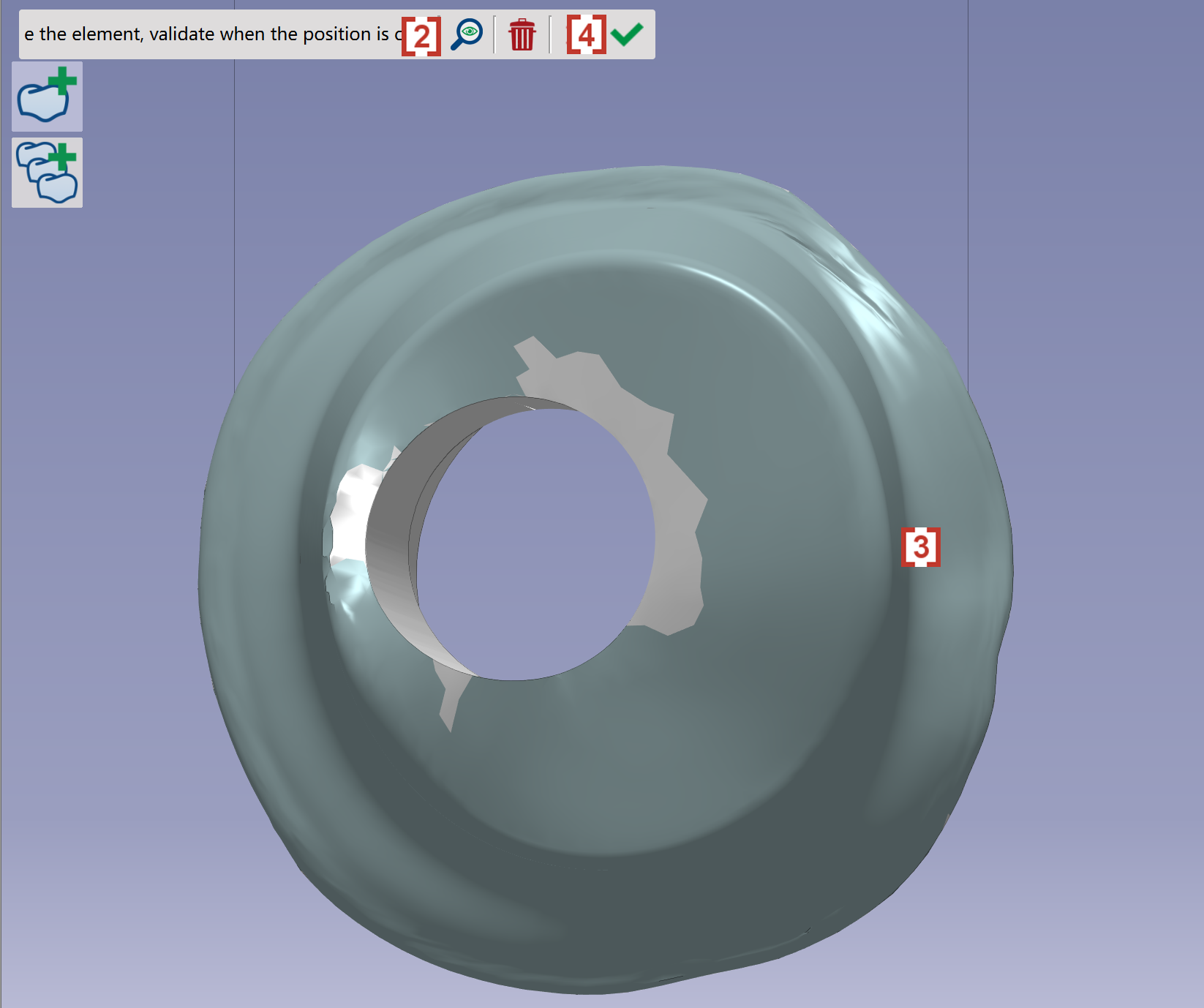
Modify the tilt of the element
|
|
|
|
|
|
|
|
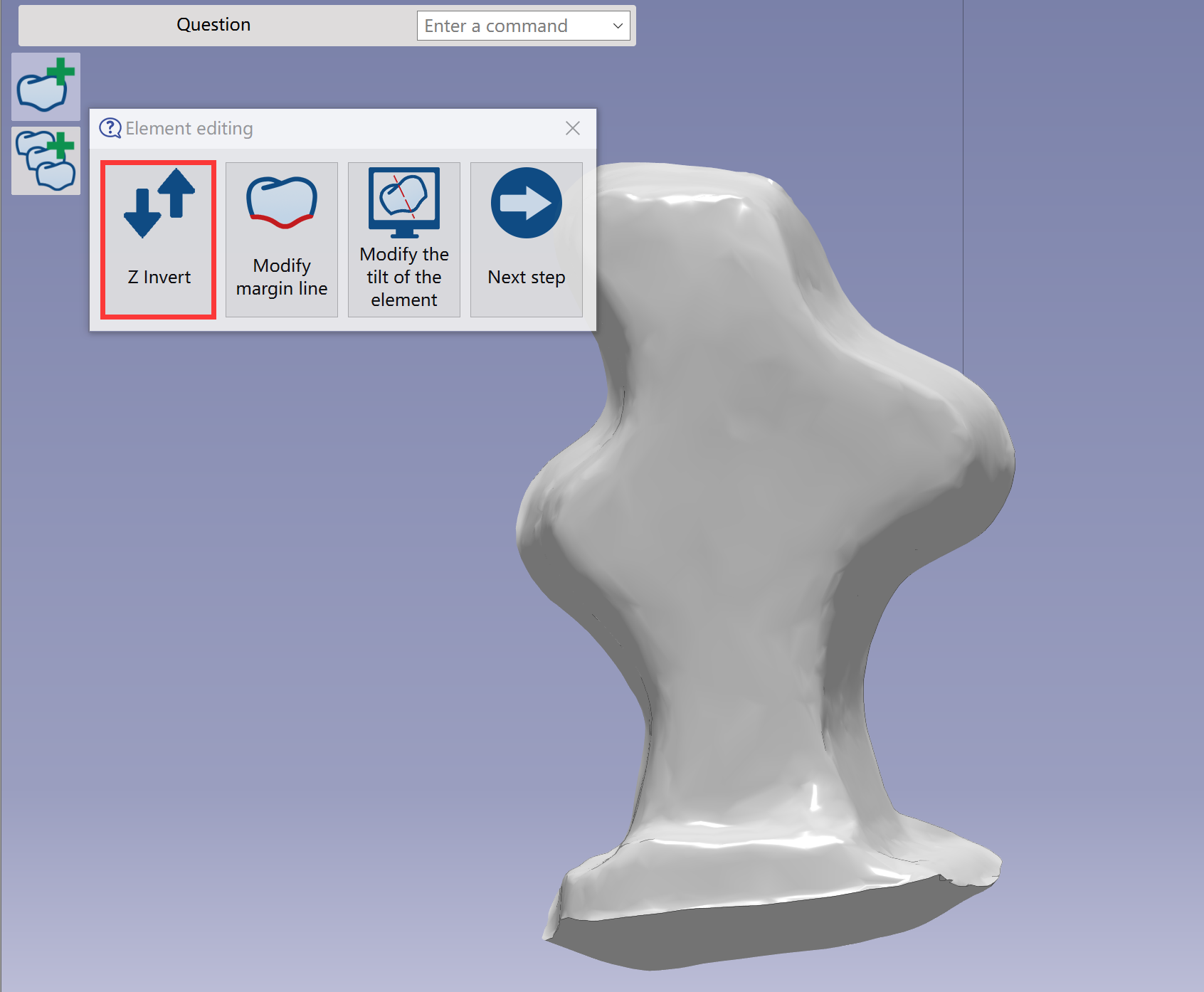
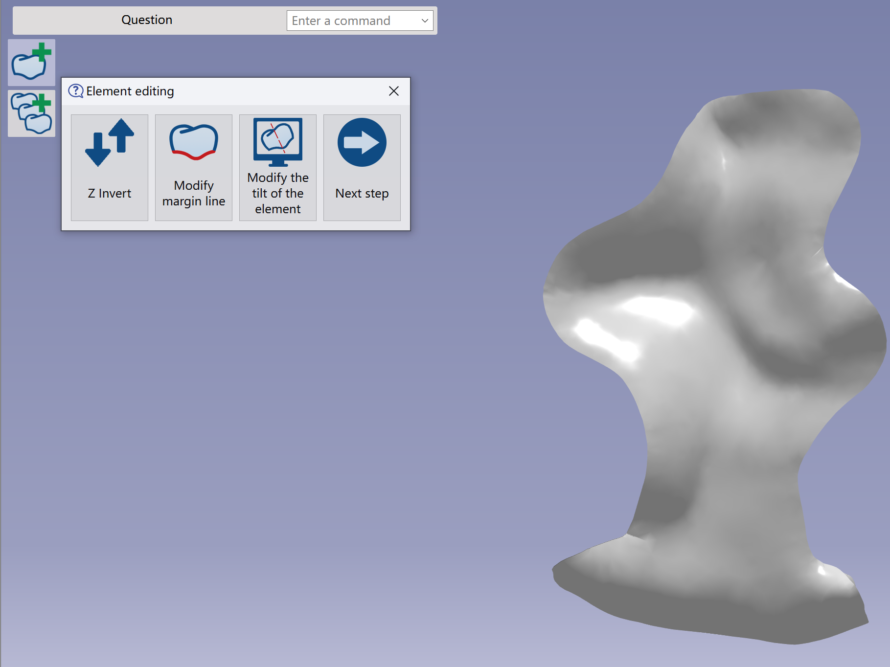
Z invert
|
|
|
|
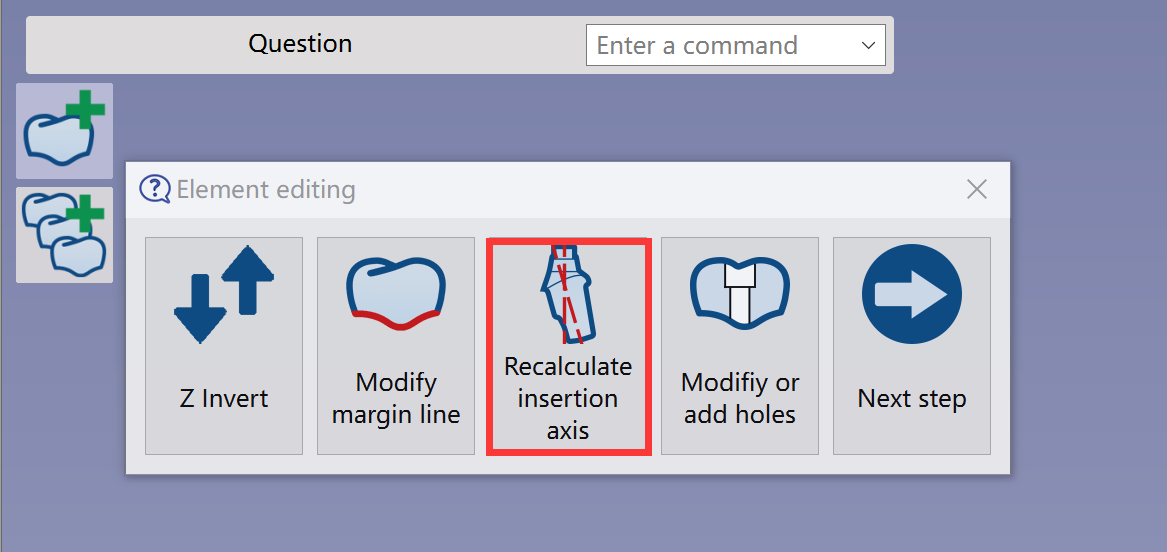
Recalculate insertion axis
|
|
|
|
|

|
|
|
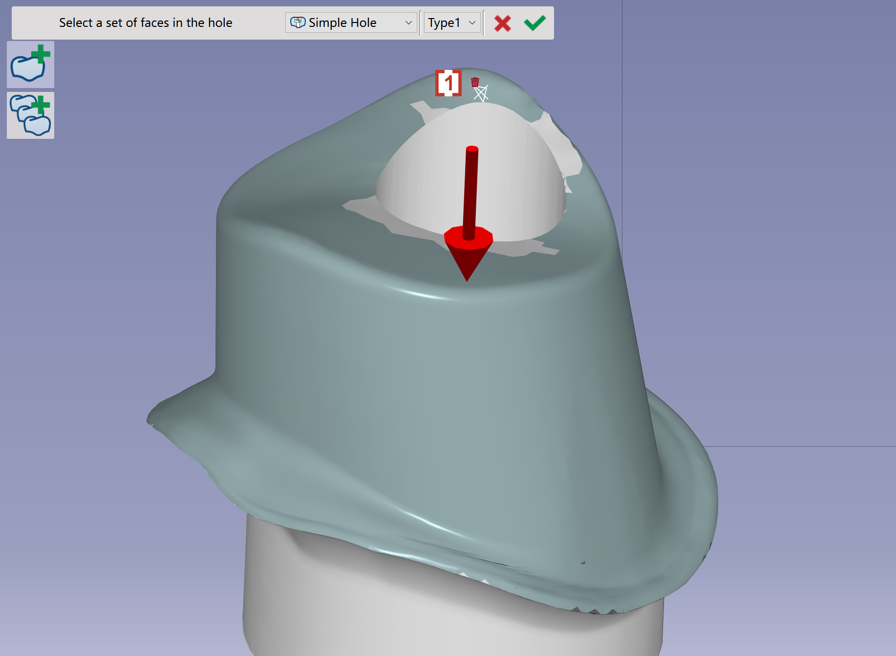
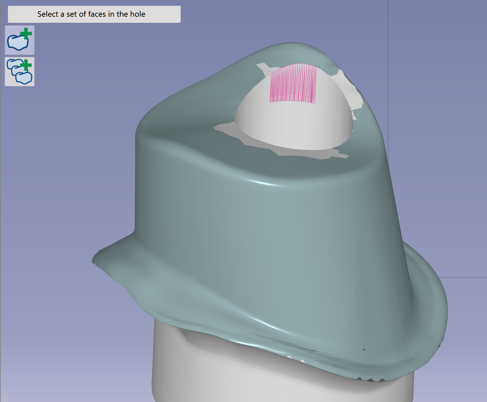
Modify or add holes
|
|
|
|
|
|