Automatic Solid Import
 | This command automatizes the import of 3D CAD model, by chaining actions necessary to prepare the machining: read the file, positioning of solid and choice of the Machine Origin, but also:
|
Automatic import of a solid (Milling or wire EDM)
 | ▶️ You can watch a video of the complete process: Click here |
1. Import
In the menu File, choose Automatic Solid Import. Select the file, then click Import. The stock is not created at this step, however a bounding box is generated to envelop the solid. | 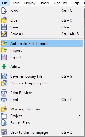 |
2. Support Face
3. Stock Dimensions
Cubic StockThe next step enables to modify the shape, the size and the position of the stock. The stock created is cubic, but you can choose a cylindric shape at this moment, By default, the stock is the bounding box of the solid with 5 mm more in the 6 directions X+, X-, Y+, Y-, Z+, Z-. You can modify this value of 5 mm, in the Margins. |
The height of stock can be modified without changing the stock height. You just have to ensure the lock is activates for Height under Sizes.
The option safety area is found in the dialog area which helps to define a safe space.
You can modify the following:
Offset value: to calculate the safety area by an offset of the stock size.
Auto bounding calculation: calculates the barycenter of part and its bounding box for a better placement of area.
Validate by clicking the Green Tick.
For more details about the definition of the stock, click here!
Cylindric stock
The process of stock dimensions is the same as cubic, except for one command.
4. Origin Position
There are 2 possibilities for positioning of the origin:
You can set the origin according to 9 predefined positions on the part by clicking on [1].
Click this icon [2] and click any edge extremity on the solid or click a face to get its barycenter. You can also click the stock.

9 Predefined positions | 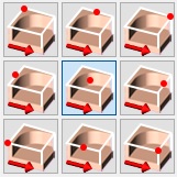 |
Click any edge extremity on the solid or click a face to get its barycenter. | 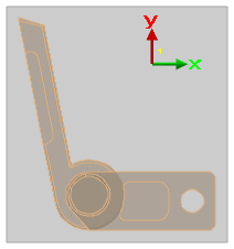 |
In those 2 cases, after selecting the point, you can move it on the Z axis with the button Altitude. By default, the origin is set at the maxi Z of part.
You can also define the origin in 2 steps: firstly click a point or choose a predefined point (reference point) and secondly give an offset on X axis (DX) or Y axis (DY) according to this reference point.

Once you validated the import, you may need to control or repair the solid(s). Several commands are available, they are presented here: Process for 3D Import
Many powerful options are included in the automatic import:
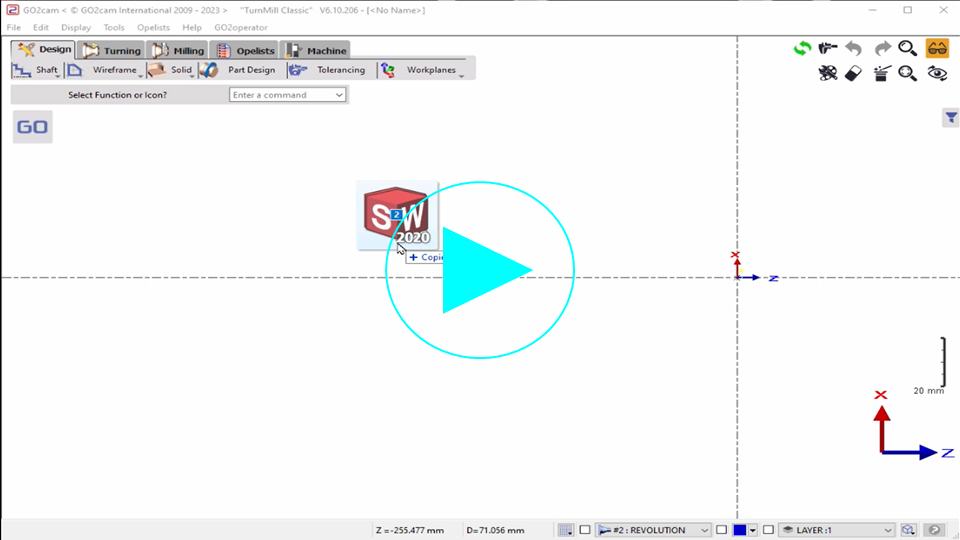
the drag and drop launches the automatic import command (instead of the standard interface),
Recent Files: files opened with the automatic command can be loaded again with the same command.
In case of creation of cylindric stock, you can recover a diameter value by clicking directly on the part.
Automatic Import of a solid (Turning)
1. Import
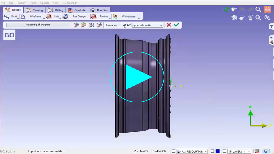
In the menu File, choose Automatic Solid Import. Select the file then click Open. The part is correctly positioned according to the revolution axis. The origin is defined on an extremity. |  | 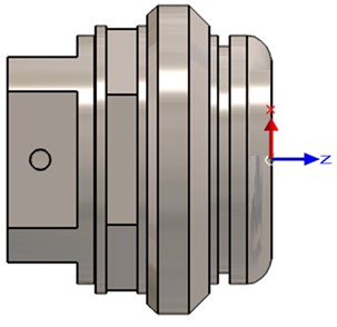 |
2. Positioning of part
You can validate the current position by clicking the green icon, or you can make some modifications, as below:
Icon | Name | Explanation |
 | Return the part | Return the part you have imported. |
 | Modify the Z Axis | To modify the revolution axis of the part if it was not correctly calculated. |
 | Turn around Z axis | To define a rotation around the Z axis (in degrees). |
 | Optimization of positioning | Option added for the Swiss Turn, with an automatized calculation to take into account non-cylindric parts. |
The calculation of silhouette is determined with the next parameters:
the field Tolerance [1] enables to modify the automatic calculation of the 2D silhouette.
the 2D Silhouette can be calculated according to 3 modes:

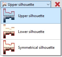
In the example below, we only clicked Return the part. You must validate the position afterwards. After validating, the 2D silhouette is automatically created, with a different color than the solid model. | 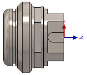 |
Note: press F11 key several times, until the 2D geometry is easy to visualize (with priority compared to solid).
If the automatic calculation of axis or silhouette fail, we give you the ability to make a simplification of the part, which may solve the issue. If the simplification gives a better result, the process of import can go on to the next stage.
3. Stock Dimensions
This step creates the stock shape and enables to modify the shape, the size and the position of the stock.

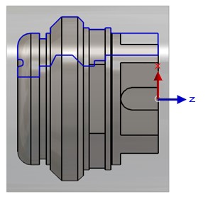
By default, the shape is a cylinder. But you can switch to 4 or 6 sides by clicking on the dropdown list [1]. Other options are given in the dialog area:
|  |
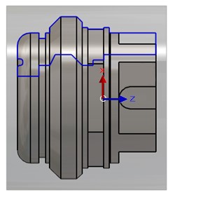
4. Origin Position

|  |
Multiple Import
Presentation
The multiple import consists in selecting several CAD files at the same time or one file including several solids. The process will be the same in both cases. The method is also identical in turning than in milling and wire EDM.
The steps are the same than in standard automatic import, we simply have one more step at the beginning: it is the treatment of the list of solids given in a table.
Generally, we face 2 situations while importing multiple solids:
import of assembly
import of a part and its stock.
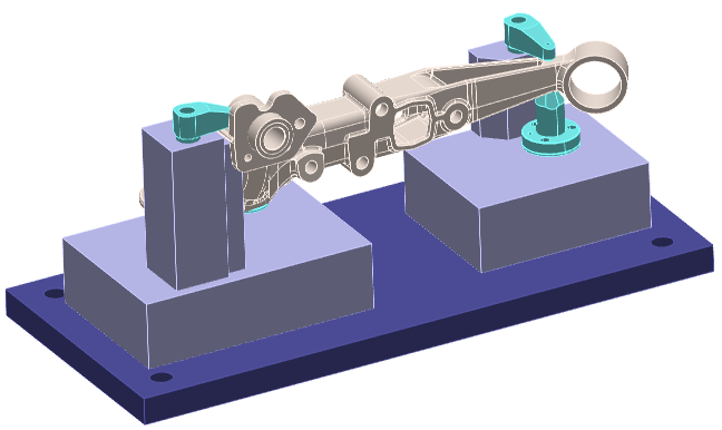
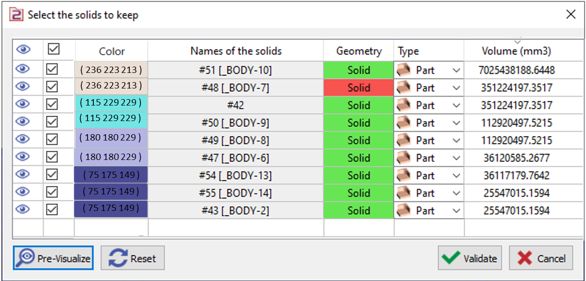
Below is a sample of imported assembly file.
 |  |
Exploitation of the table
Each line of the table is a solid. The solids are sorted from the bigger to the smaller. The volume in mm3 is given in the last column. You can also click a solid on the screen and find it selected in the table.
The cells enable several actions for the preparation of the file:
 | Visibility | Clicking on this icon enables to make a solid being invisible/visible. Even if it is invisible, it will be selected for the import if we validate at this stage. | |
 | Selection for the import | The box is checked by default, all the solids are selected for the import if we validate like this. But if you ‘uncheck’ one box of solid, then it is not taken for the import. In this case, the Red Cross icon is displayed in the column of visibility, the show that the solid is removed from the process. | |
Color of the Solid | You now have a new column ‘color’ that helps you to identify the color of the solid during multiple import. It is particular useful to identify which solid needs to be kept. The code of the color is also listed. | ||
Names of the solids | Names of the solids are now read and displayed in the table. If the solid has no name, the name of file is given. | ||
Geometry | Geometric type of the element, it can be solid, wireframe or surface. The color of the cell gives extra information about the ‘quality’ of the element. In green the element is correct, in red a problem has been detected. Either you will have to use repairing commands on the element after the import, or you can remove it now from the import if it is not a necessary element. | ||
Type | Here, the purpose is to define the use of the element later in GO2cam. The cell offers 4 possibilities: Part: solid to machine, Stock: the solid(s) selected are automatically transformed into machining stock, Symbol: selection of work-holding and clamping elements, Other: solid to keep but which is not of any other of the 3 families. While creating the automatic stock, this element will not be taken for the calculation of the bounding box. For example, it can be the origin, which is sometimes designed as a solid. The choice can be done solid by solid, which is probably often the case for part and stock. But it is also possible to make a multiple selection and accede to the popup menu to choose the type of element. You can read more explanation in next page. | 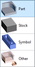 | |
The buttons, at the bottom of the table, enable general actions:
 | Pre-Visualize: cancels the hide commands so that you can see the elements that will be effectively imported. |
 | Reset: all the actions previously done (hide, selection, type of elements…) are cancelled and reset. |
 | Validate: when the treatment is complete, click on validate to go next step. |
 | Cancel: this button enables to exit from the automatic import command. However, the import is not cancelled, the solids are imported but without any treatment for positioning and stock and origin creation. |
Clicking on the Headers also enable some actions, from left to right:
Visibility / Invisibility of ALL elements at once,
Cancel / Validate ALL elements,
Sort by solids names,
Sort by type of geometry,
Sort by type of element,
Sort by decreasing / increasing values of volumes.
Example of treatment
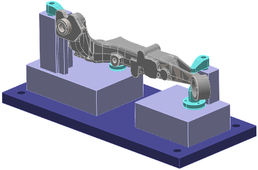
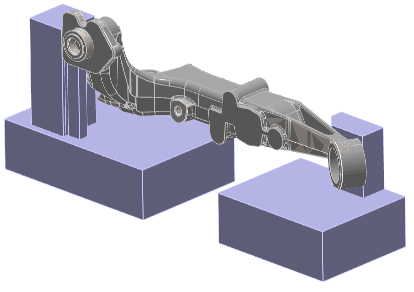
This assembly includes the part with its cast stock, and some clamping elements: The second solid (the dark blue plate) is not correct. It is not considered as a useful element, we cancel it from the import, The 4 clamping elements are hidden, The types ‘Part’, ‘Stock’ and ‘Symbol’ have been given to the different elements. The part with its holding device is ready for machining. | 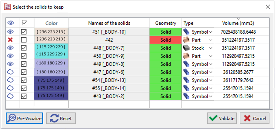 |
 |  |
Popup Menu
A right-click on one or several lines enable to accede to some actions, with the advantage of the multiple selection:
We also find the commands of Deletion and Hide. | 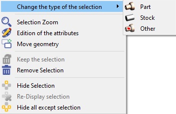 |


