FAQ - Machining Generalities
How can I check the coordinates of machining during the simulation? |
|
The coordinates are displayed in the button of same name, in the dialogue area of simulations.  Many interesting complementary information here: Simulation |
How to invert the direction of profiles while selecting the geometry for machining? | |
| |
Once a profile or multiple profiles are defined for machining, you can invert it by selecting the white cursor icon, called ‘Information’ in Milling and Wire EDM and ‘Activation of a profile’ in Turning.  Then click the profile itself or the profile label. This will invert the selected profile. Or, if you want to invert multiple selected profiles in one go:  Then right-click in the background and select Invert All. This will invert all the selected profiles without having to click on each of them one by one. For additional information about inversion of profiles, click here!(Milling) or here! (Turning) |  |
Is it possible to automatically reference strategy Tool and Stock allowance parameters for pocket rework? | |
The wizard can be used to automatically obtain these references. After calculating the pocket cycle, select the strategy and the tool for the rework cycle (for instance pocket rework) before selecting the geometry. In geometry selection, click on the wizard icon and then select the pocket cycle. The reference diameter and stock allowances are automatically read by GO2cam in the reference cycle and applied in the rework cycle. |  |
How to manually define a Cast stock? | |
If you want to use a stand-alone stock in GO2cam to machine a component, you can do this by creating a separate solid. For example, you can use the 2D geometry functions to extract the edges from your solid, post-process the shape with the 2D functions, and then extrude the finalized shape into a solid model. | |
1. First of all, load your model to be edited into GO2cam and set the support face, the stock, and the origin as usual. Initially, the dimension of the stock is not of importance. | 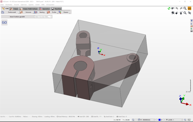 |
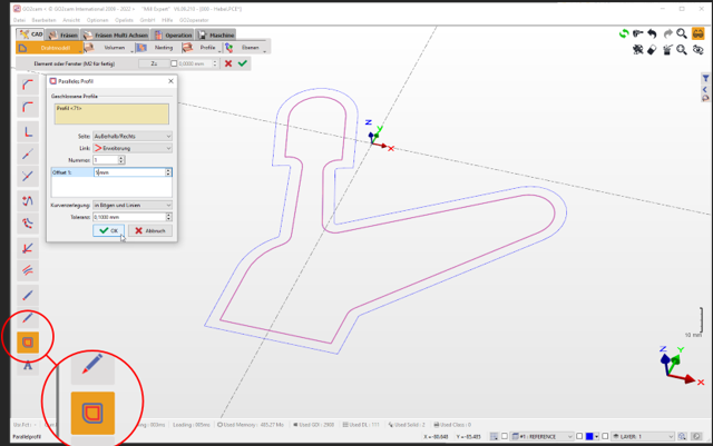
2. You can use the edges extraction command to extract the outer edges of the model and then simplify them accordingly, e.g. create an offset contour for the desired measurement... | 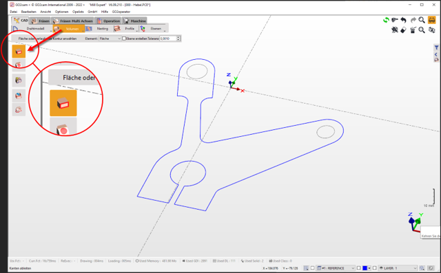 |
 | |
3. Using the Solid Extrusion command, you can now extrude the profile to generate a 3D solid. NOTE: This process could have also been done by using the face offset command to offset the faces of the workpiece to generate a separate solid. | 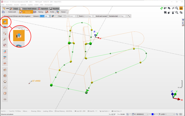 |
4. You can now define the newly generated solid as a stock as per below: Switch to the "Milling" tab (1). Double-click on "Stock" in the machining tree (2) In the command line, select the command "Stock from a solid" (3) and select the solid(4) You will be prompted to ‘Keep the solid history?’. It is recommended to select yes since this will allow to automatically update the solid if any modifications is done to the wireframe. | 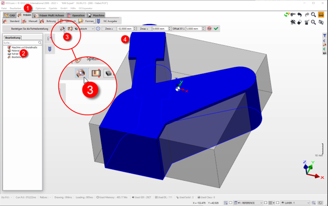 |
The existing cubic stock is automatically replaced with the 3D stock. If you change the parameters of the automatic stock after this, the stock will revert back to default cubic. | 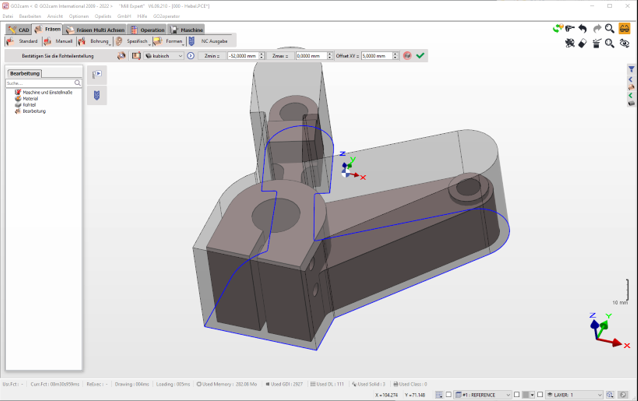 |
You can see very clearly that GO2cam calculates the tool paths respecting the shape of the existing stock and thus avoids air machining. 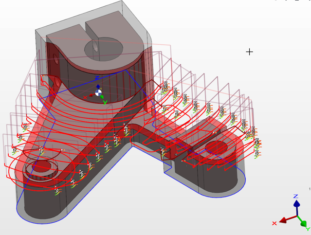 | |
What is Stock Compacting? | |
The objective is to calculate only the most recent stock result from the preceding operation in order to condense the stock. However, since the evolving stock is not updated, the single cycle update may be incorrect. |
How can we change tools during an operation ? | |
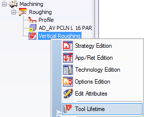
In GO2cam you have the ability to change the tool during a machining cycle! The change can be manual or automatic (tool changer). This command is very useful when machining operations are very long : such as Vertical turning of big parts or 3 axis machining of a hard material, where the tool wear occurs rapidly and we need to replace it during the operation. Access it by: | |
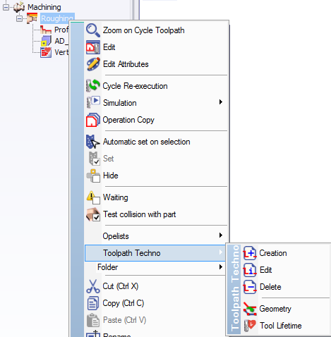 |
|
▶️ You can watch a video on Tool Life Management: |  |
I just modified my vice, but it hasn't changed on my project, why? | |
After any modification, you must update the symbols like vice, toolholder or chuck. For this, go back to the project and then to Edit>Database>Symbols update. This will take into account all the latest changes done to symbols. |  |


