Import
Presentation
 | The command Import enables to read the CAD files and load them in GO2cam. All the types of files are read, 2D and 3D, but not any treatment is applied during this import stage. |
2D Files
When you import a 2D file, a dialog is open with several options. The video here describes the different options available: |  |
When you validate, the file is read and the geometry is positioned in GO2cam as it was defined originally in the CAD system. The file contains every element including the ones that are not useful for machining.
Many commands enable to position and cleanup the wireframe geometry.
The process for a 2D file import and the use of those commands is presented here: Process for 2D Import
Dxf/Dwg Import: Our log report highlights the count of circles with unique centers.
For instance, if a file includes 20 circles, but only 14 distinct centers, it indicates there are 14 distinct holes within the part.
3D Files
When you import a 3D file, a dialog is open with several options.
Importing a X_T file is done without any option, no dialog is opened. | 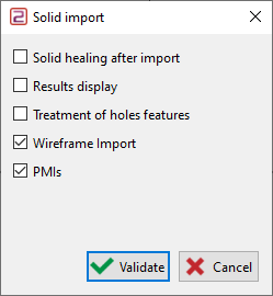 |
When you validate, the file is read and the solid geometry is positioned in GO2cam as it was defined originally in the CAD system.
Many commands enable to position or repair the solid(s) if necessary. The process for a 3D file import and the use of those commands is presented here: Process for 3D Import
Special process for a turning part
What is specific with a turning or a mill-turning part is the positioning of the part according to ZX workplane. Another topic is that 2D geometry is necessary to program the turning operations, while the solid is necessary for milling.
The rules to respect are the following:
The axis of revolution must be the Z axis,
The 2D geometry for turning must be in the Revolution Plane,
The solid must stay in the Reference plane.
Process:
1. Import of the part
Most of the solid models imported are positioned according to the XY workplane. We need to move the part so that the revolution axis is corresponding to the Z axis of the reference plane. | 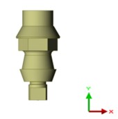 |
2. Positioning in ZX direction, still in the Reference Plane
Go to the menu Import Repairing. Choose the command Part Positioning, the solid is automatically selected. Click a face (pink color on the example), the solid is automatically repositioned, and still in the reference plane. | 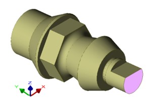 | 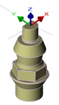 |
3. Creation of the turning geometry
Firstly, change the current plane and choose Revolution. |  | 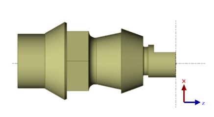 |
Go to the menu Solid / Wireframe Choose the command Silhouette and select the option Revolution as a mode of calculation: Click on Validate, the 2D geometry is created in the Revolution Plane, for turning operations. |  | 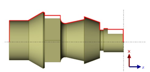 |
