Safety Area
Introduction
 | In GO2cam, the safety area is a boundary to which the tool is withdrawn when a repositioning, level change, or tool change is to be performed. The motion of the tool is limited to the area set. |
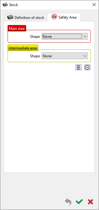
 | The command is accessible in the Stock Definition dialog box, under the Safety Area tab. In previous versions (V6.10 and before), the command was accessible in the tab for origin definition during Automatic Solid Import or a specific command on right-clicking on Stock in the machining tree. |  |
| ||
| ||
 | The tab provides the settings to define the bounding safety box for the Main area and the Intermediate area. As from V6.11, the dialogs have been modified, including the name of some of the options. | |
The Main area defines the safety area surrounding the stock based on the Shape chosen. Depending on that, the radius/diameter and the length can be defined, and the Axis of reference chosen accordingly. A Margin value can also be applied on the bounding area | ||
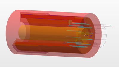
The Intermediate area defines an internal safety area, for example for hollow bodies. The internal bounding area is represented by an orange/yellowish body. The parameters are identical to that of the Main area. |  | |
The center of the safety area can be defined manually by picking a point or by inserting a specific coordinate. Clicking on Center automatically will relocate the safety area at the geometric center of the part. | ||
Types of Safety Area
The types of safety area that can be defined for both Main area and Intermediate area are as per below:
Sphere | In this case, the stock is enveloped with a sphere around the center of gravity of the component. The toolpaths are extended up to the boundary. |
Cylinder | The boundary envelope is defined similarly to the sphere but with a cylindrical shape. Additionally, the axis of the cylinder and its length can also be modified. This type is ideal for turning components. |
Workplane on Cylinder | With this option, only the outer surface of the cylinder is taken into account. Operations not passing through that surface( for instance in this case the ‘top’ operations) end at the positions set in the cycle. All other machining operations end up to a "virtual" plane, which is always placed on the cylinder face normal to the machining direction. |
Reference Plane | In this case, a safety plane area is generated accordingly based on the reference axis, up to which all toolpaths are then extended to. Toolpaths that do not touch this plane will not be affected. |
Workplane on Sphere | With the Workplane on Sphere, you get a universal tool for defining the safety areas. Here, the sphere option and the plane option are combined in one setting resulting in the optimal setting for milled components. |
Movement
The Movement parameter allows to modify the direction of the approach and retract toolpath with 2 options:
Machining Z
Perpendicular
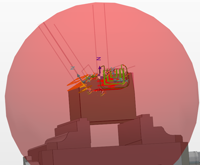
Machining Z - the rapid motion of the tool follows the current Z direction of the cycle up to the safety area. |  |
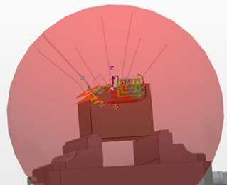
Perpendicular - the rapid motion of the tool after the completion of the cycle rapid motion, follows a direction perpendicular (Normal) to the surface of the safety area envelope. This usually generates a kink in the toolpath also minimizing the travel distance to the safety area. |  |

