
Presentation
|
|
This command enables to select a clamping element and position it on the current workpiece. Clamping elements can be vices, clamps and any support component. |
Your elements can be defined in the environment called Clamping / Toolholders. You can design them or import solids. More information about this creation process: Creation of Components.
1. Import a Vice
|
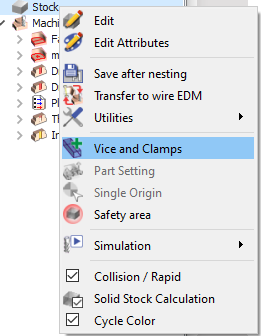
To import a vice and position it, follow those steps: In the Machining tree, do a right-click on line Stock and select “Vice and Clamps”. |
|
|
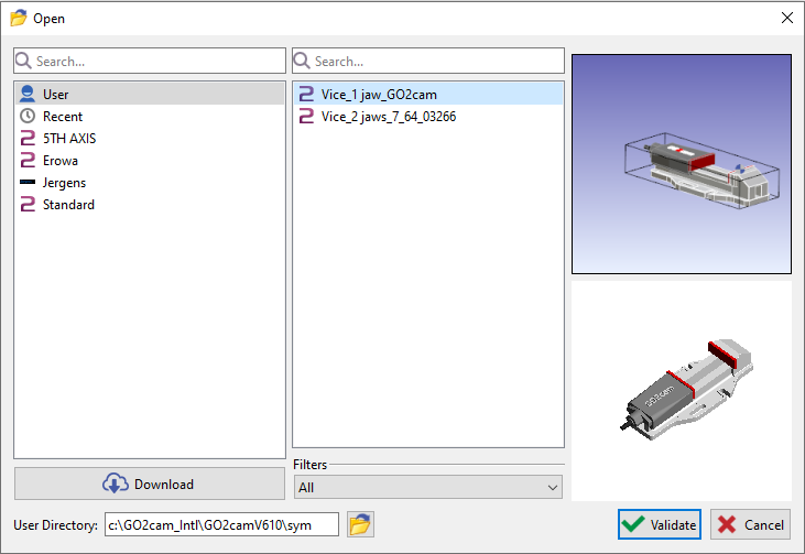
Select the vice from the list and validate.
You can select the element from several libraries:
|
|
|
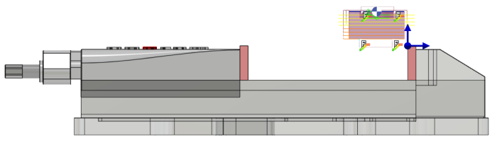
Adjust the position according to the origin if needed and click on the “Green Tick” to validate. |
|
|
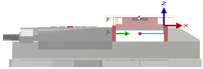
You can further adjust the vice if you need to rotate or translate the vise to secure your workpiece. You can either use X, Y, Z axis or insert the values in the corresponding field to translate the vice. Click on the “Green Tick” to validate. |
|
2. Case of a Vice with Multiple Tightening
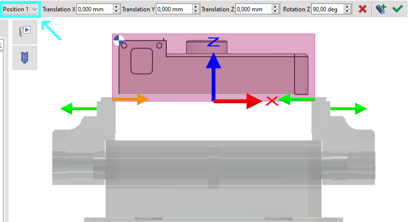
Some vice have several possible positions of tightening the part. In that situation, a new field appears in the dialog area and enables to choose the position.
|
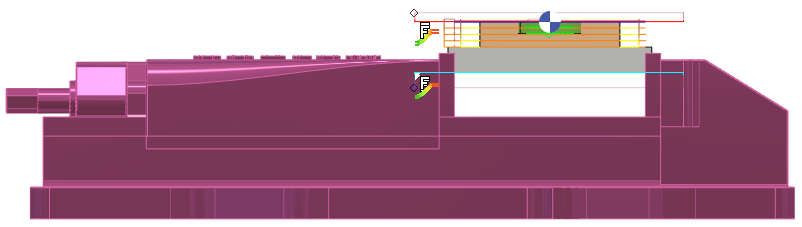
Here, Position 1 is selected. The part is too large and the jaws go out of their room. |
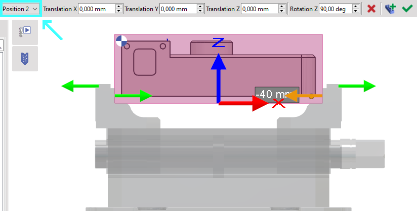
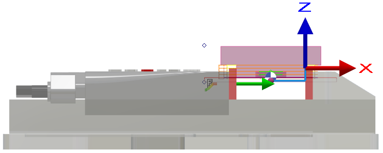
We switch to Position 2 and we can see that it is much better. Note that the position in Z is directly given by the system of axis defined during the vice creation. |
|
|
|
▶️ This video shows how to create a vise with Multi-tightening and how to use it on a solid.
|
3. Special Case: Flip-Flap of a part
|
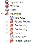
You will have to associate the vice to the part setting “Top Face” and “Back Face”. |
|
|
|
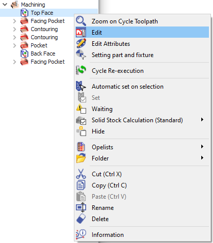
To associate the vice to the Top face: Right click on the “Top Face” and Edit |
|
|
|
Click on the “Symbol associated to the setting” and select the vice. Click twice on the “Green Tick” to confirm the selection and Validate. Click on Update and Total. |
|
|
|
|
Change the Plane from ‘Reference’ to ‘Back Face’ |
|
|
Repeat the steps to import a vice and aligned it with the back face of the workpiece. |
|
|
|
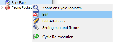
To associate the vice to the Back face: Right click on the “Back Face” and Edit |
|
|
|
Click on the “Symbol associated to the setting” and select the vice. Click twice on the “Green Tick” to confirm the selection and Validate. Click on Update and Total. |
|
|
|
▶️ You can watch a video on Vice Setting for Top Face and Back Face:

|