
|
|
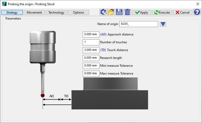
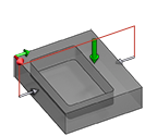
Probing on the stock to define the part origin. When the cycle is run, the probe comes to touch the face to identify the center. The toolpath can be visualized in the simulation. |
It is also possible to click wireframe geometry for the definition of the probing.
|
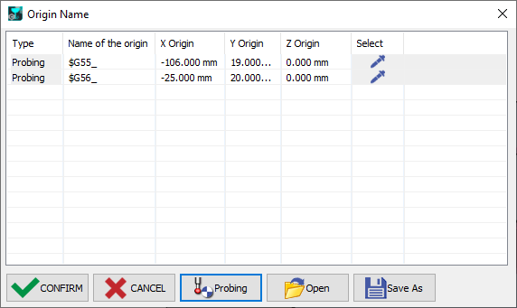
Each probing type selected generates a separate machining cycle. It is possible to use multiple probing types to define one origin ( so as to obtain the x, y and z coordinates):
The name of the origin defined in the Strategy must be the same for both probing cycles so as to link them together. The combination of both cycles will define the WCS coordinates position in the controller. |
|
|
Click on Probing to generate the Origin lists for the probing cycles. The origins WCS need to be created in parallel to use for programming and for outputting in NC codes. |
|
Types of Probing
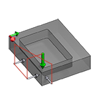
Defined at Center of rectangle |
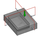
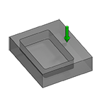
Defined at Center of rectangular pocket |
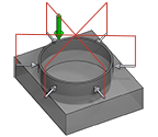
Defined at Center of cylinder |
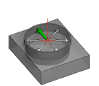
Defined at Center of cylinder pocket |
Definition on a Z altitude |
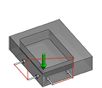
Definition on a rectangular corner |
Definition on a rectangular corner |
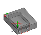
Definition on a rectangular corner |
Definition on a rectangular corner |
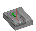
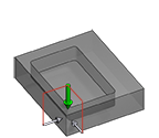
Definition on middle of rectangle in X |
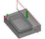
Definition on middle of rectangle in Y |
|
Strategy Parameters
|
Dialog Area |
Parameters |
|
|
Parameters |
||
|
|
||
Movement Parameters
|
Dialog Area |
Parameters |
|
|
Safety (in Z) |
||
|
Approach and return in Z |
Retract between touches |
Move between touches |
Technology Parameters
|
Dialog Area |
Parameters |
|
|
Cutting Conditions |
Feedrate |
|
|
Tool number |
Specific Number |
|
|
Length compensation number |
Diameter compens. Nb |
|
|
Users Fields |
Comment |
Control Device |
|
Milling Set |
|
|
Options Parameters
|
Dialog Area |
Parameters |
|
|
Behaviour on the clamps and components |
||