
General workflow
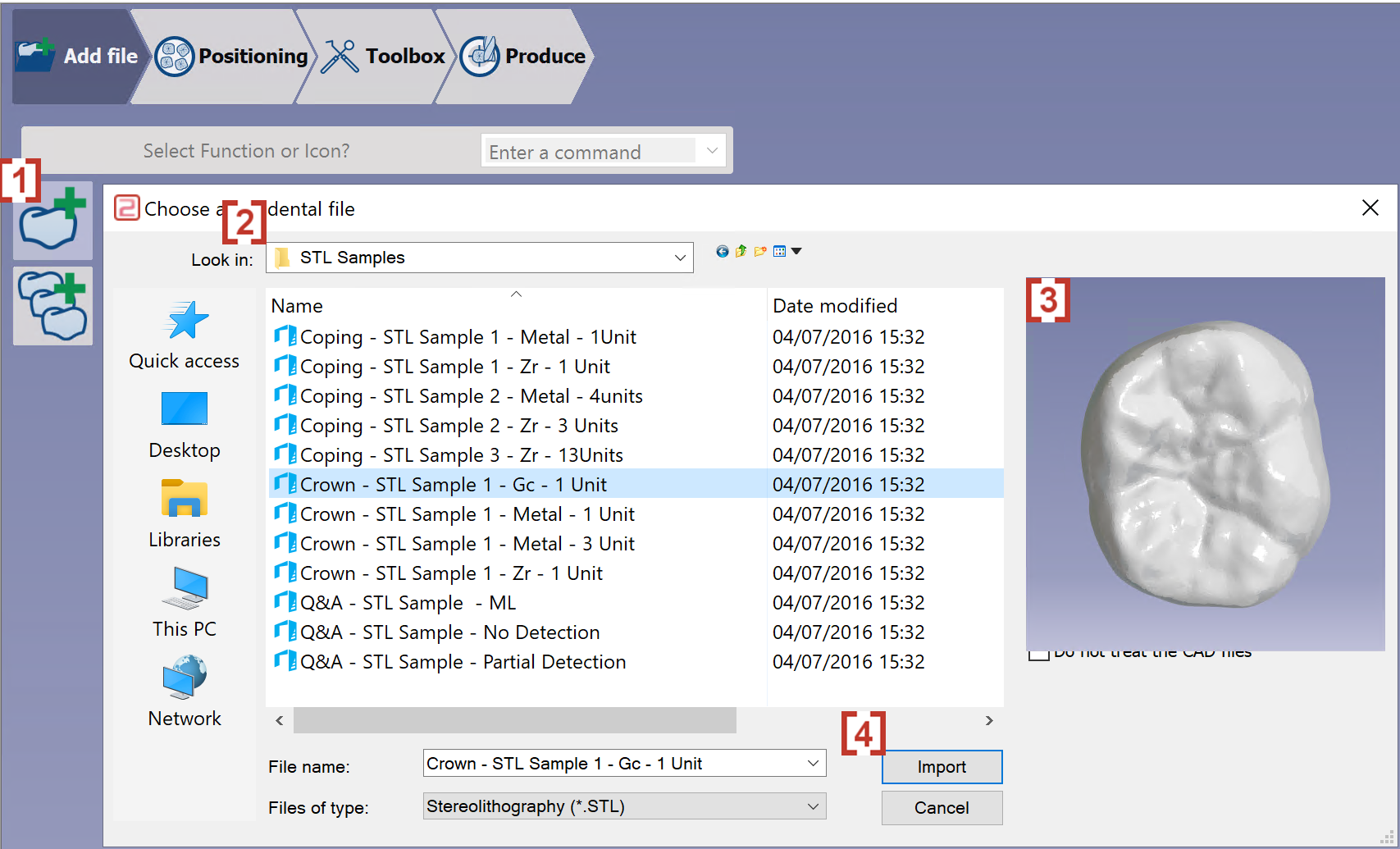
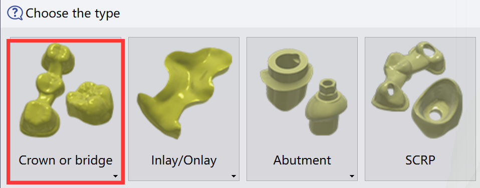
Import of an STL file
|
|
|
|
Validation of the import
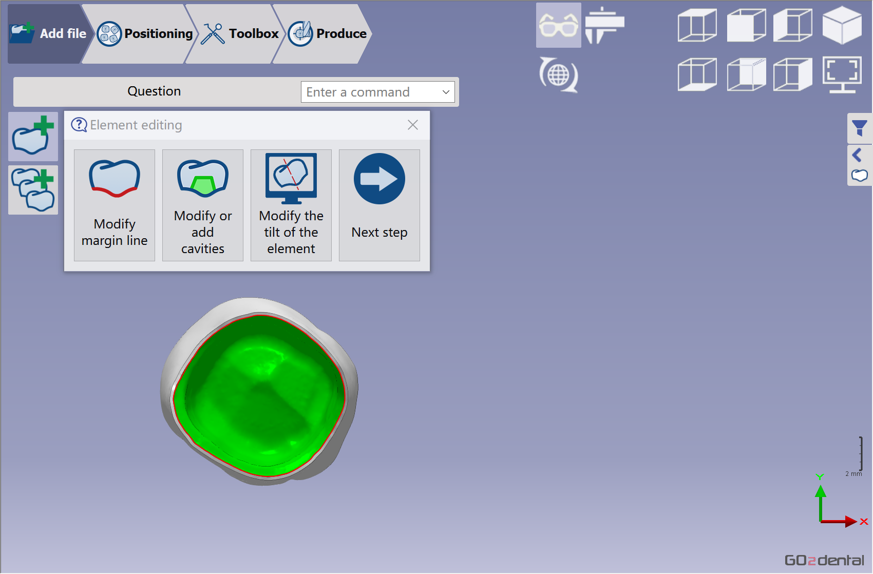
|
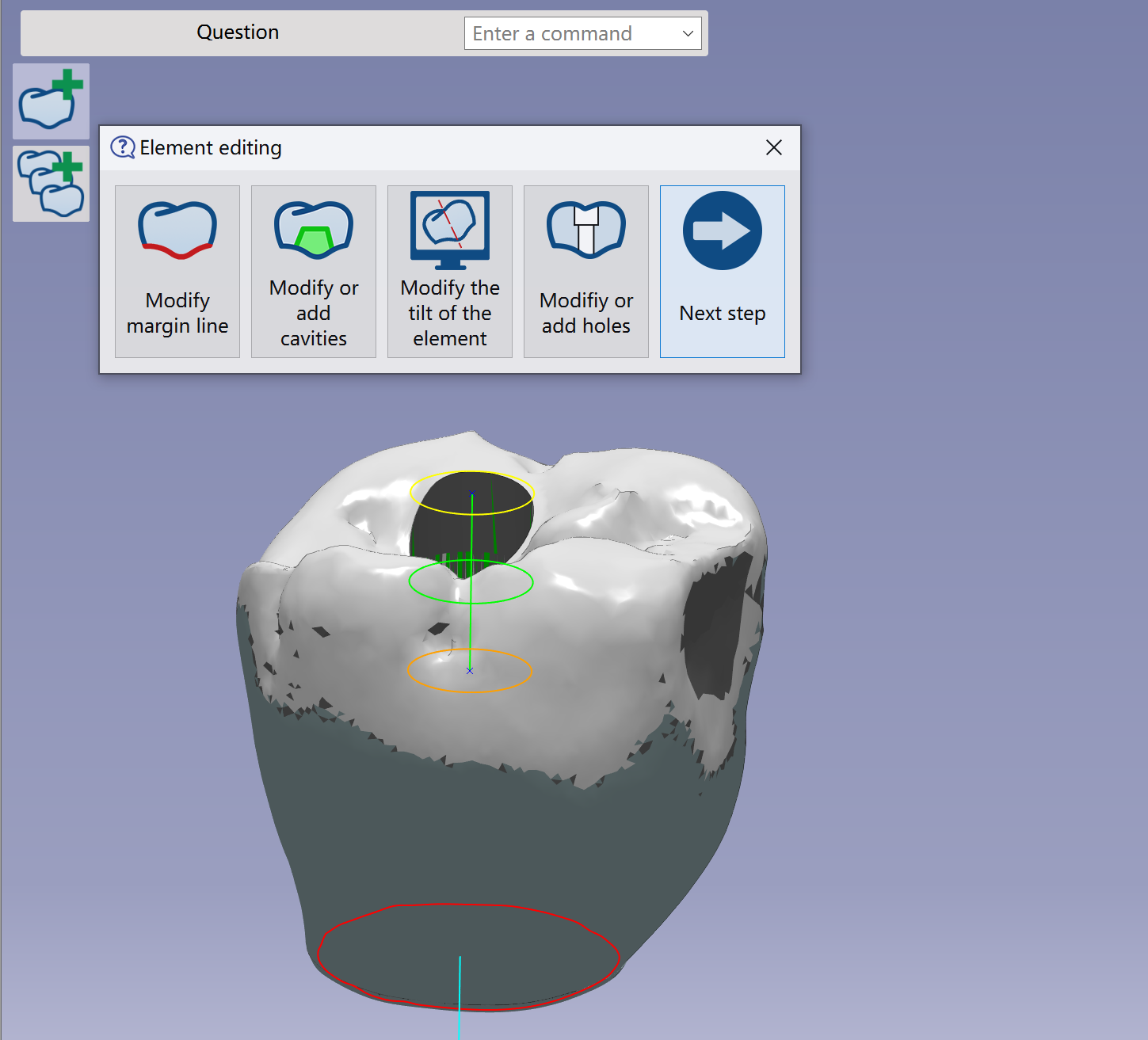
Verify the element was imported correctly and validate it. Next, edit the element to modify the margin line, cavity, or tilt.
See more details about these functions in Add File Functions | Element Editing |
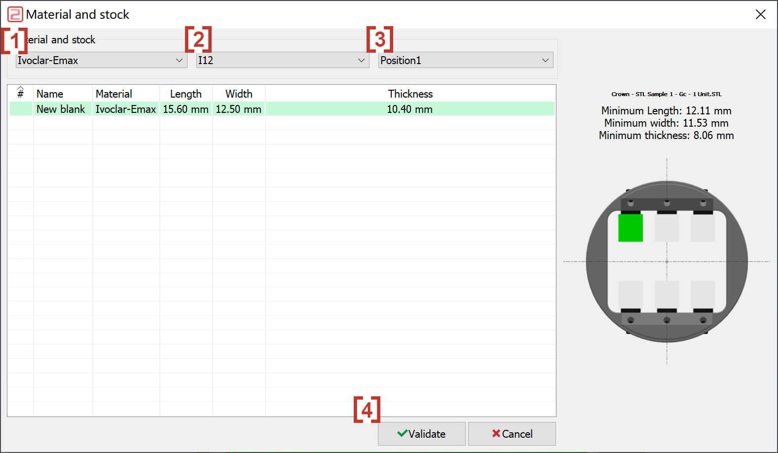
Material selection
|
A dialog box opens to select the material...
|
|
Placement of the STL file
|
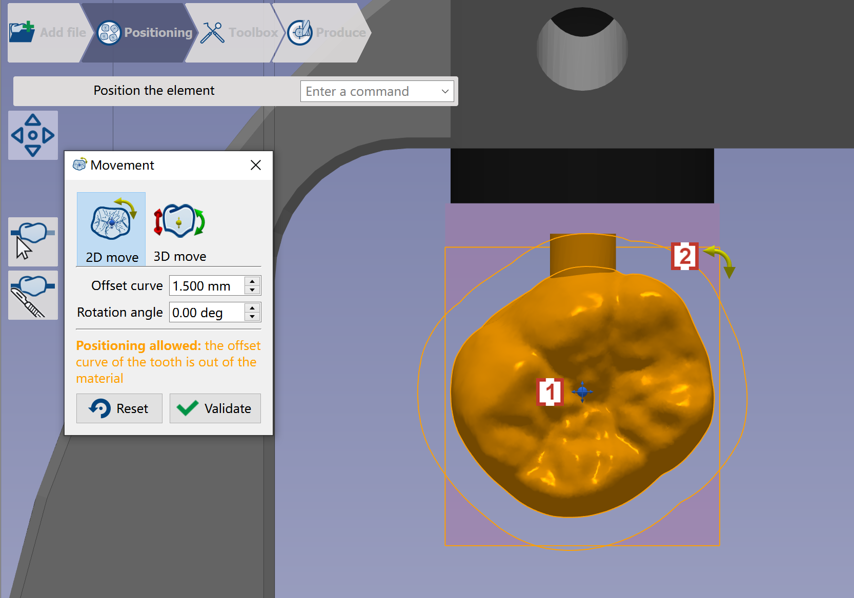
Position the element in the material. Go2dental automatically places the STL file near the material's end face to save machining time. Users can use Manual Nesting
|
|
|
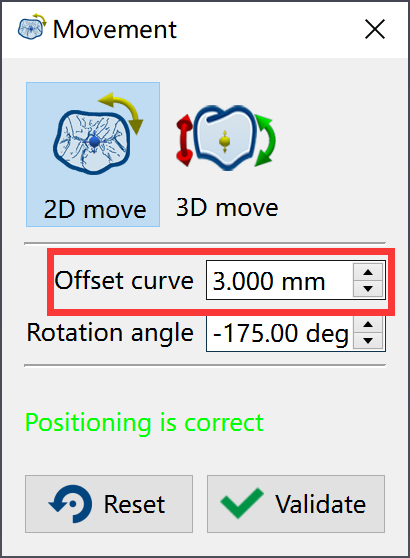
You can define the offset between the element and the exterior curve.
|
|
Creation of connectors
|
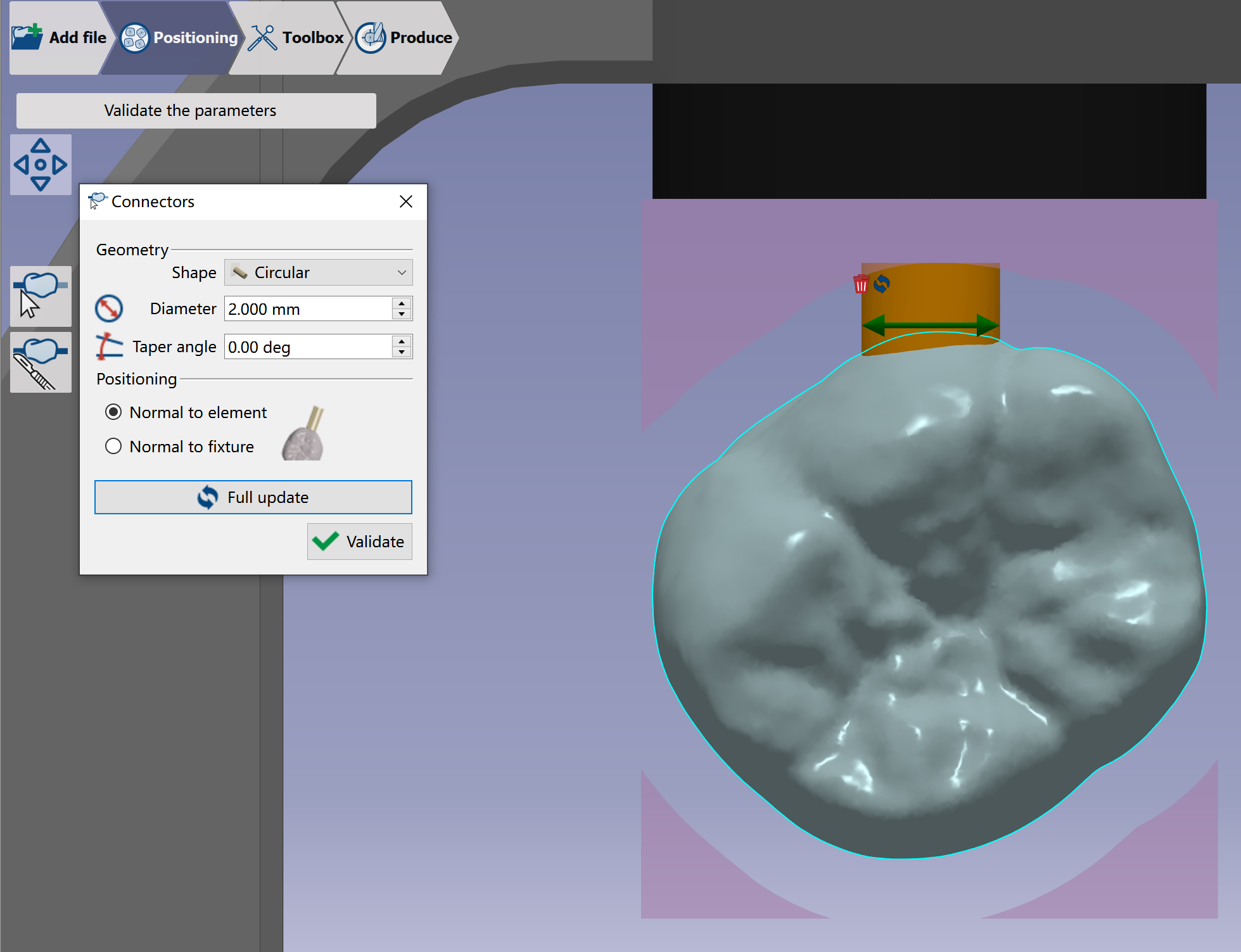
When the user validates, the software calculates automatically the placement in Z which is optimized according to the undercut line. Check more details of Positioning Functions | Manual connector – Blocks |
|
|
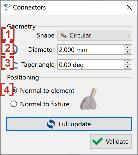
Users can change connector parameters.
|
|
|
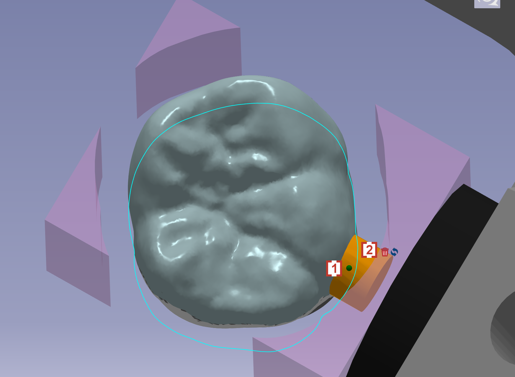
The user can place connectors in 3D by dragging the green point. The user can move the connector with icon [1] or delete the connector directly with icon [2]
|
|
Selection of the milling strategy
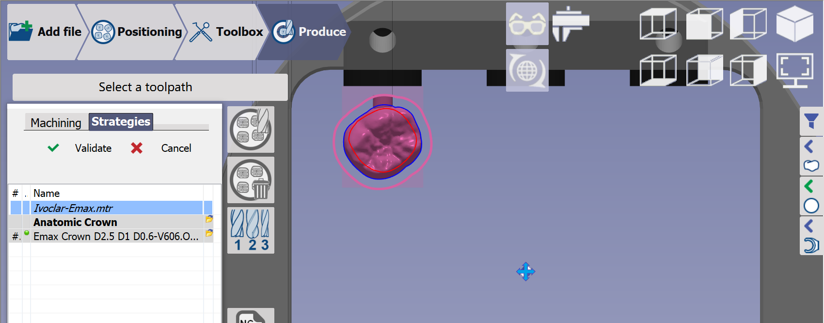
|
GO2dental calculates the toolpaths and generates the NC program. |
|
You can also apply strategies by right-clicking the STL: |
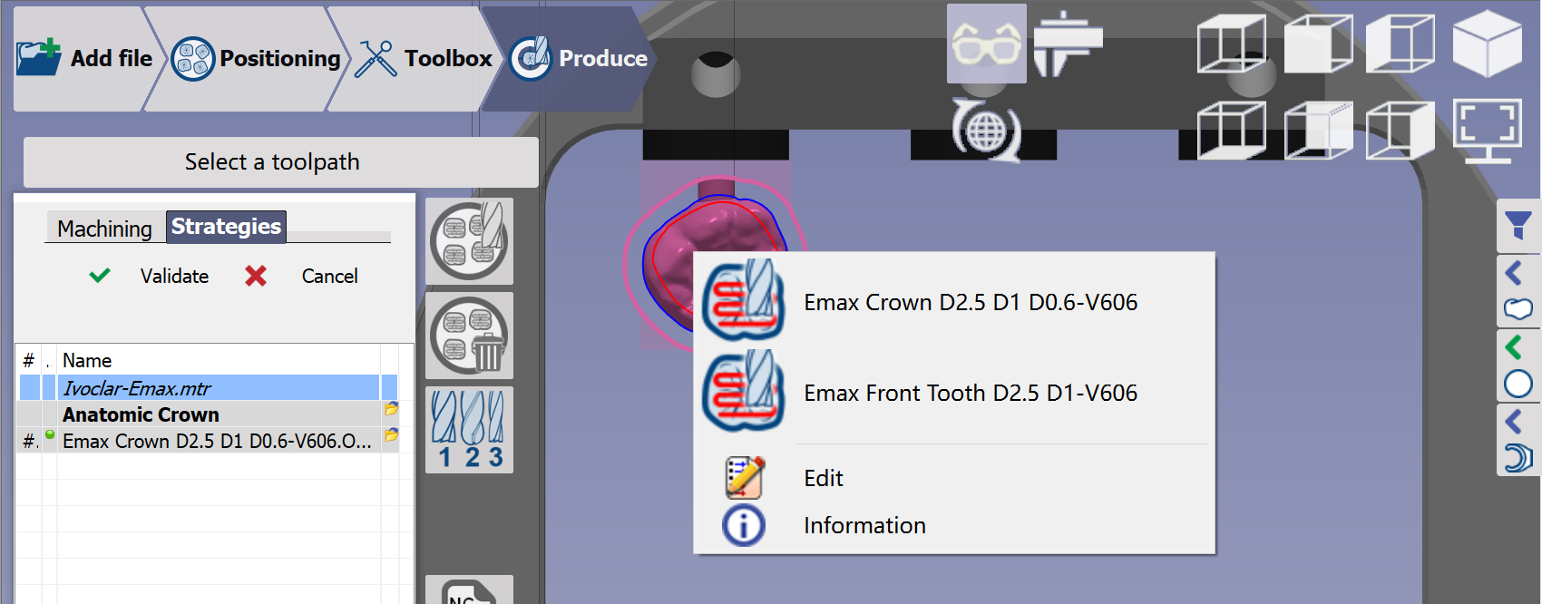
|
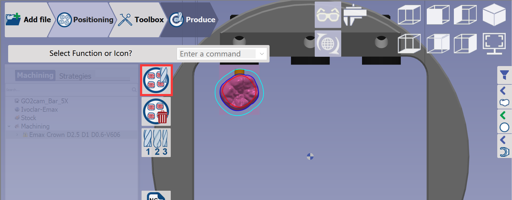
Calculation of Toolpaths
|
Click the 'calculation of toolpaths' button and wait for the calculation to finish. |
|
Summaries and documentations
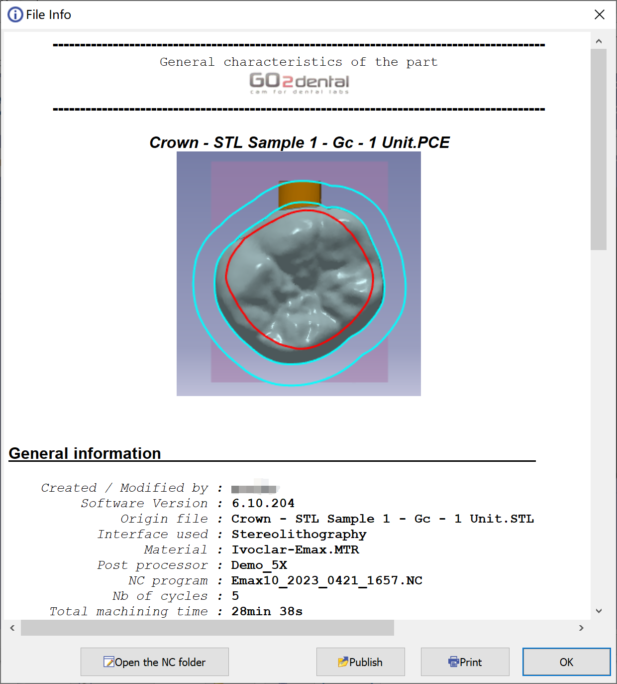
|
This sheet shows the theoretical milling time and summarizes the tools, material, and machine configuration used. Click "Open the NC folder" to access the NC program in the ISO folder. |
Please save the PCE file when starting a new process or exiting the software. Our engineer can check the toolpath using the PCE file if you encounter any problems.
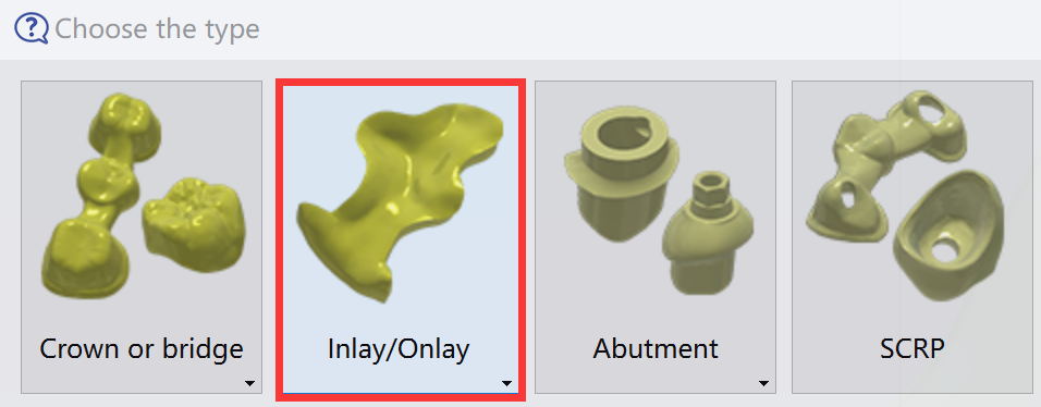
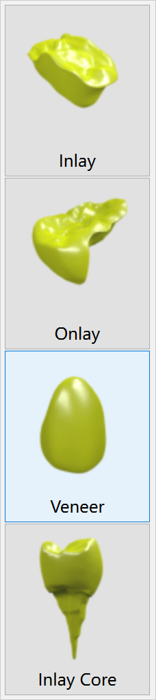
Workflow of Inlay/Veneer
Here, we show only the different processes in the Inlay/Veneer workflow. The other processes match the general workflow.
Import of an STL file
|
|
|
|
Validation of the import
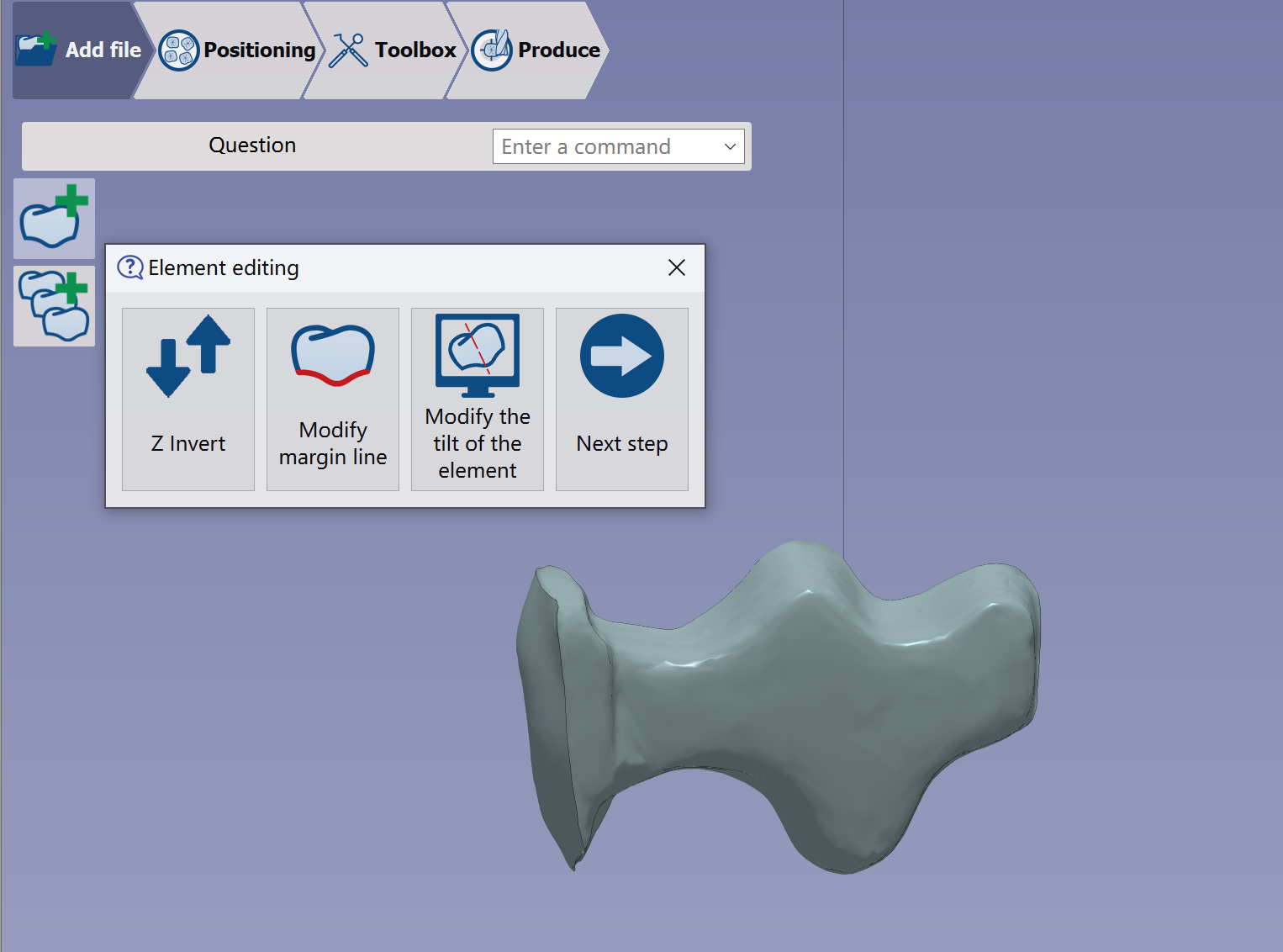
|
Verify the element is correctly imported and valid. Next, edit the element to invert Z, adjust the margin line, or tilt it.
See more details in Add File Functions | Element Editing |
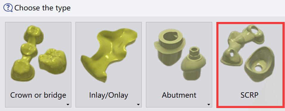
Workflow of SCRP
Here we show only the different processes in the SCRP workflow. The other processes are the same as in the general workflow.
Import of an STL file
|
|
Validation of the import
|
|
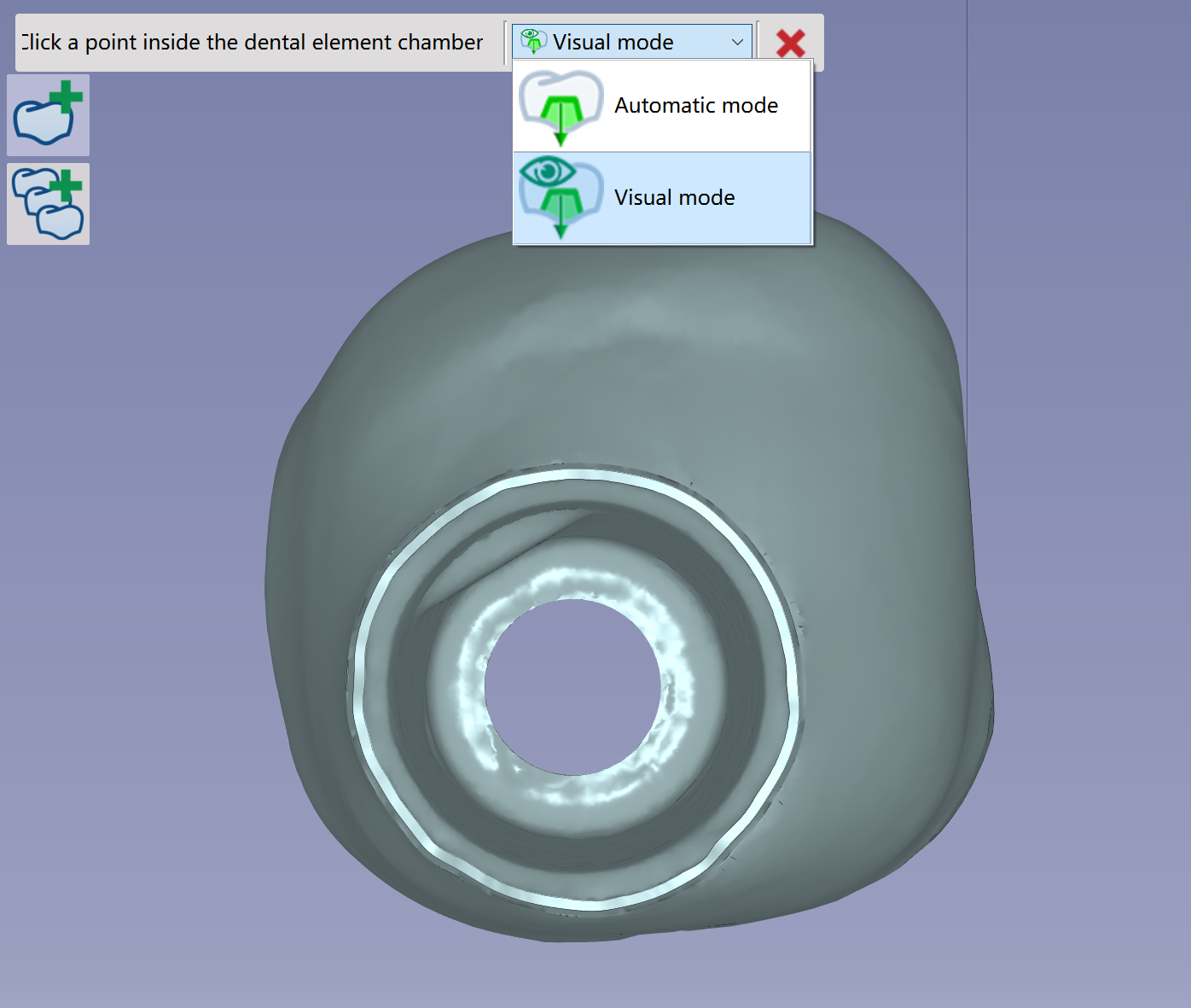
Use Automatic or Visual mode to set the SCRP element's insertion axis. The SCRP cavity will be machined with a 5X toolpath using the defined insertion axis as the tool axis. |
|
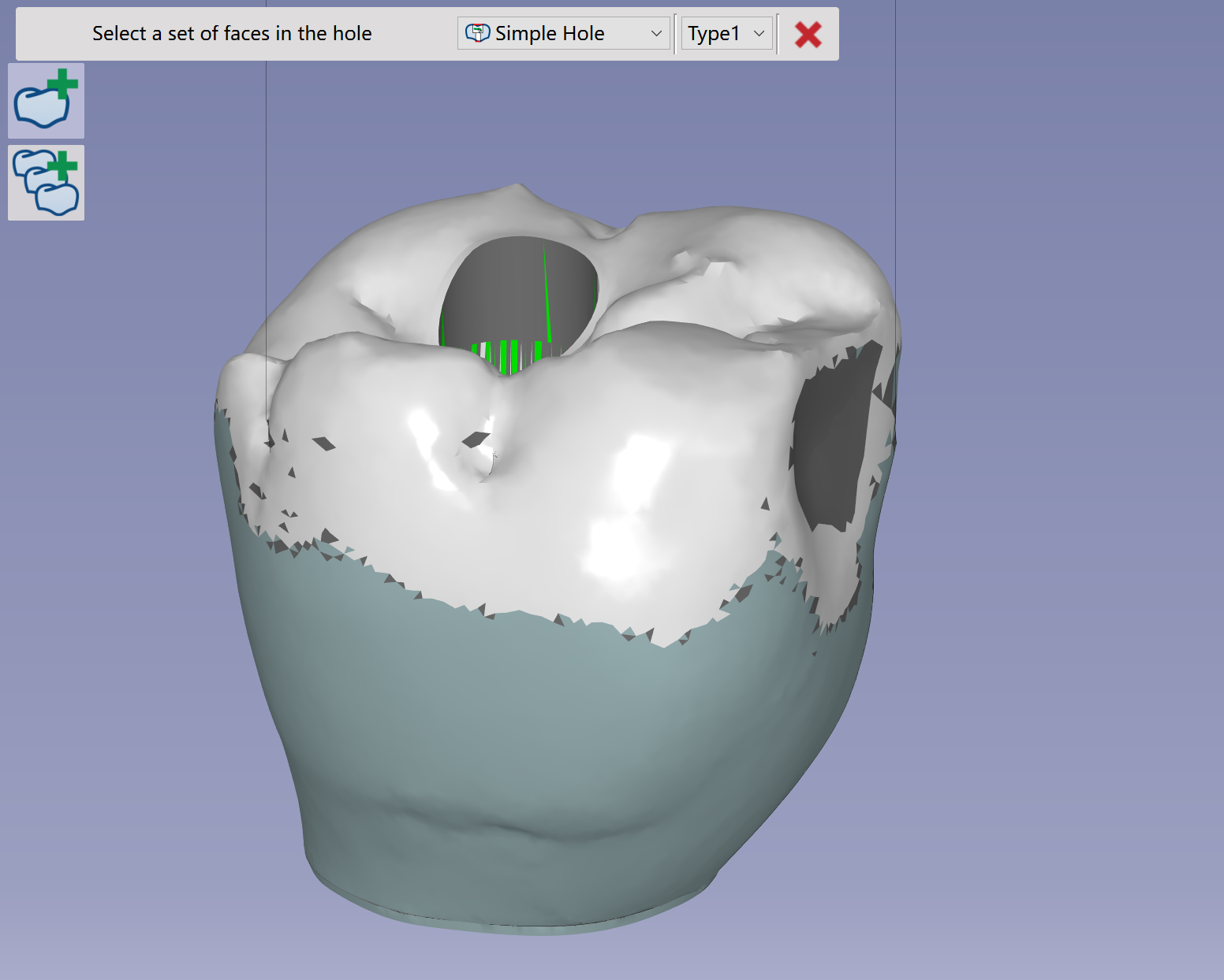
Rotate the SCRP so the occlusion side faces upward. |
|
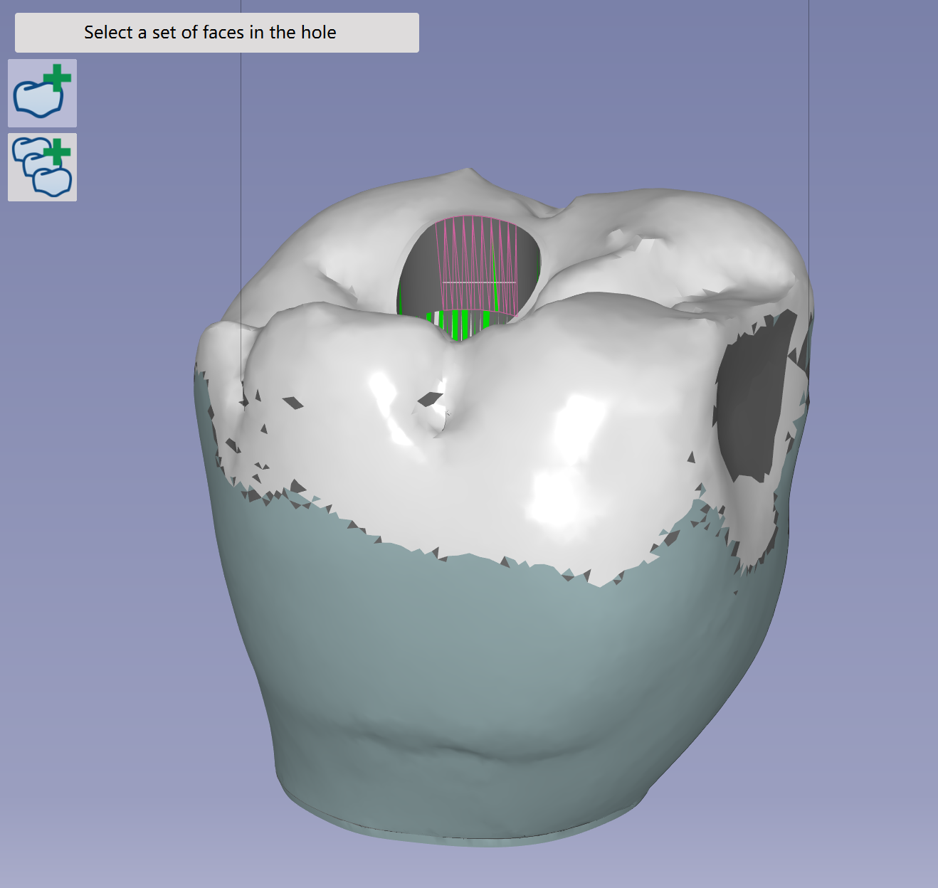
Click the inner face of the hole, then streak along it. The hole feature will be recognized. |
|
Verify the element was imported correctly and validate it. Next, edit the element to modify the margin line, invert Z, adjust holes, or recalculate the insertion axis.
Check more details of the functions in Add File Functions | Element Editing. |