
General workflow
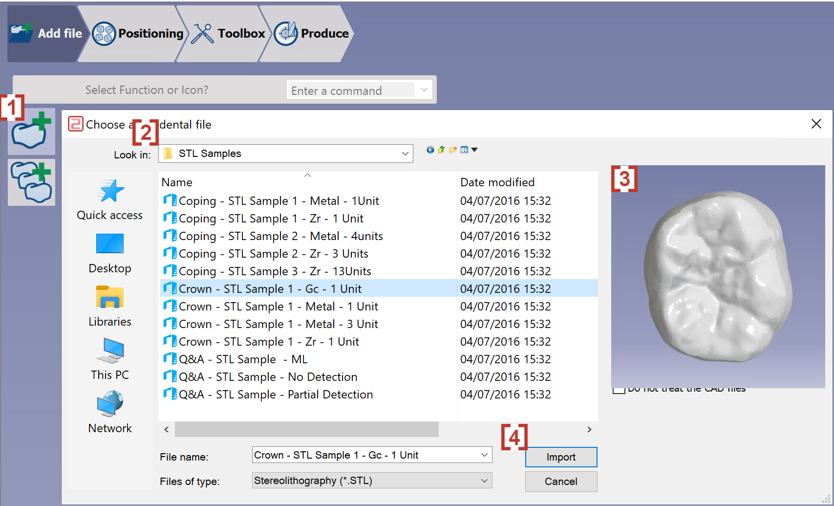
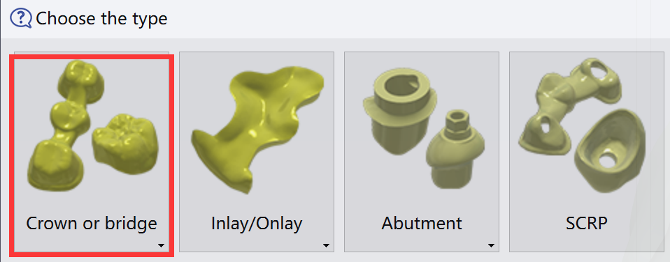
Import of an STL file
|
|
|
|
Validation of the import
|
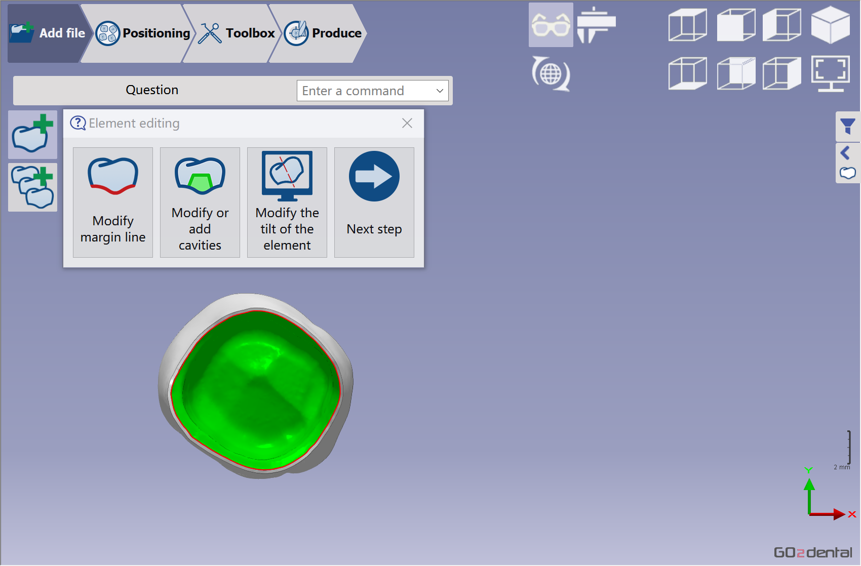
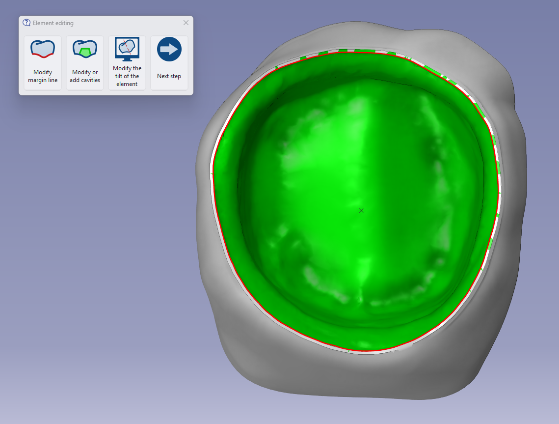
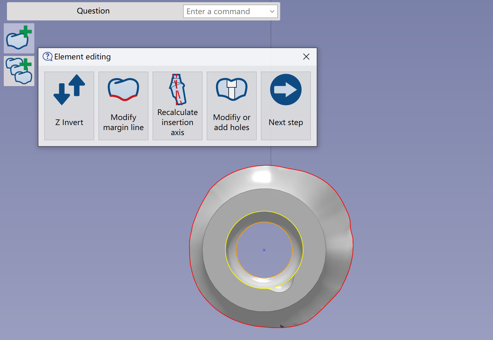
Verify that the element has been correctly imported and validate. The next step is to Element editing in order to modify margin line, cavity or tilt of element.
Check more details of the functions in Add File Functions | Element Editing |
|
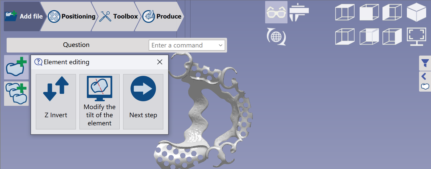
If imported elements lack margin lines or cavities, the Element editing function defaults to Z Invert instead of Modify margin line and Modify or add cavities. Ensure the lingual part appears on the opposite view. Use the Z invert function to correct this.
|
Positioning along Z
|
We need to carefully check the STL direction along the Z axis. During STL import, surfaces requiring higher quality, such as the margin line or interface connection of implants, must face us. If the surface is incorrectly oriented along the Z axis, we can use the Z invert function to correct it. After importing the STL, it will be placed upside down in the disk material so that the high-quality surface rests at the bottom. All elements will have the occlusion side on top of the disk material. |
|
Material selection
|
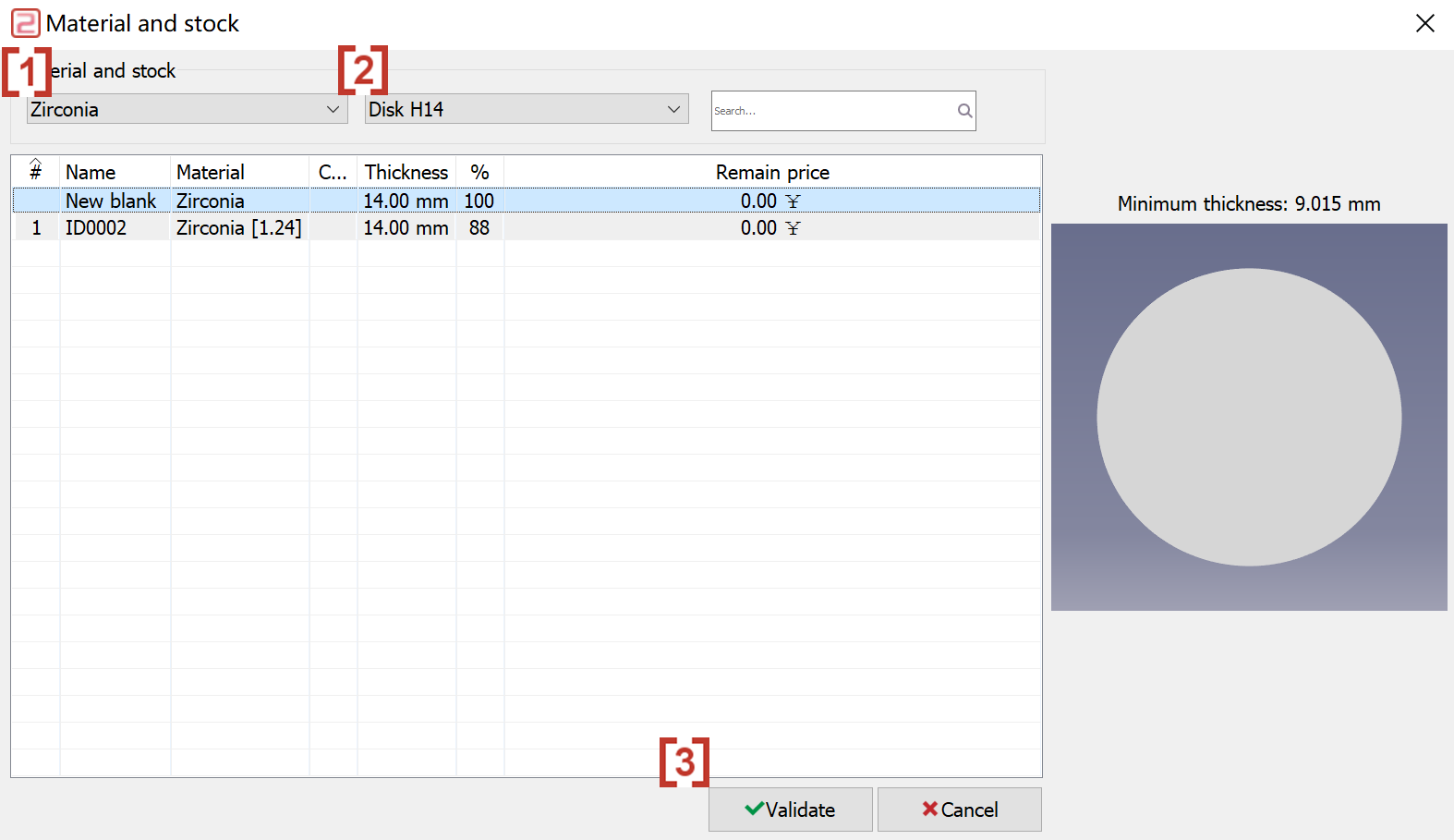
A dialog box opens to select the material.
You can also use Management of blanks to create your own Disk material library. |
|
Placement of the STL file
|
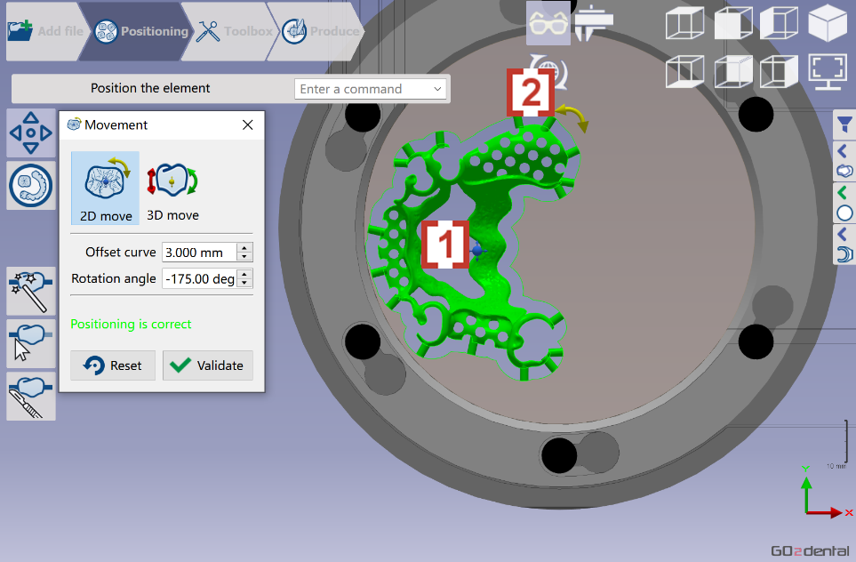
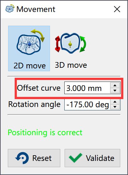
Position the element in the disc. Go2dental automatically places the STL file in the material. Users can reposition and rotate it if needed:
|
|
|
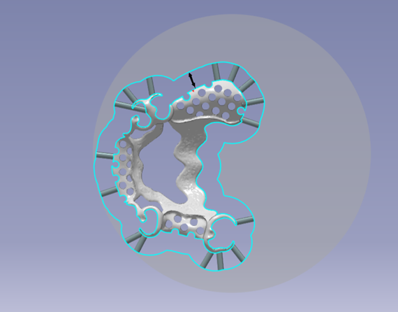
You can define the offset between the element and the exterior curve*. For an optimal tool path during roughing, define the offset as follows: Tool diameter x 1.5 The exterior curve defines the milling area. If the position is correct, click validate. |
|
Creation of connectors
|
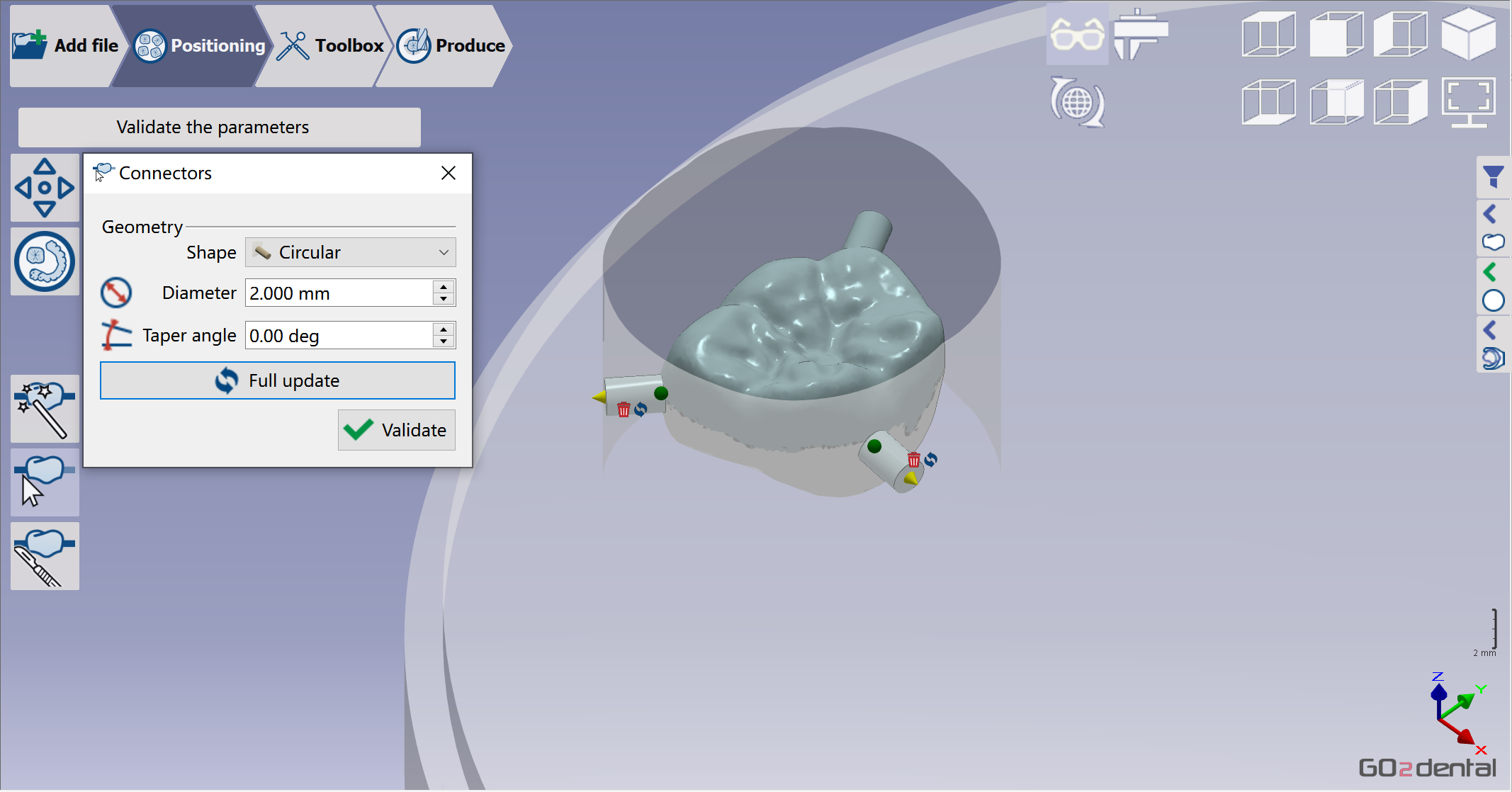
When the user validates, the software automatically calculates the optimized placement in Z based on the undercut line. |
|
|
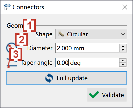
Users can customize connector parameters.
|
|
|
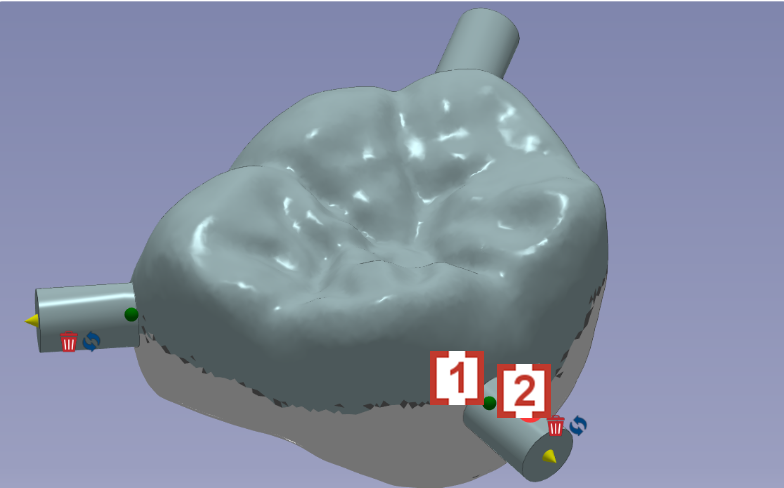
The user also can place the connectors at his convenience in 3D by dragging the green point. The user can move the connector with icon [1] or delete the connector directly with icon [2]
|
|
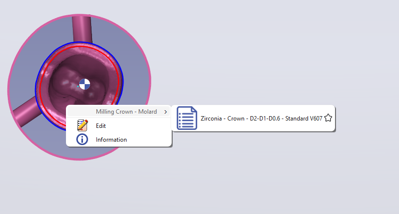
Selection of the Milling Strategy
|
|
GO2cam Dental calculates toolpaths and generates the NC program. |
|
You can also apply strategies by right-clicking the STL: |
|
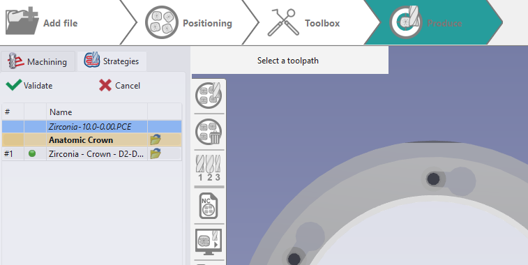
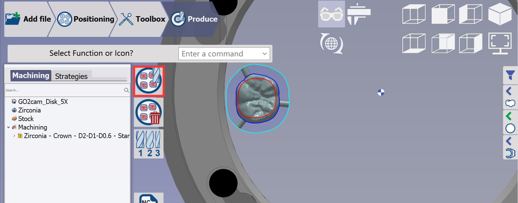
Calculation of Toolpaths
|
Click at button 'calculation of toolpaths' and wait until the calculation ends. |
|
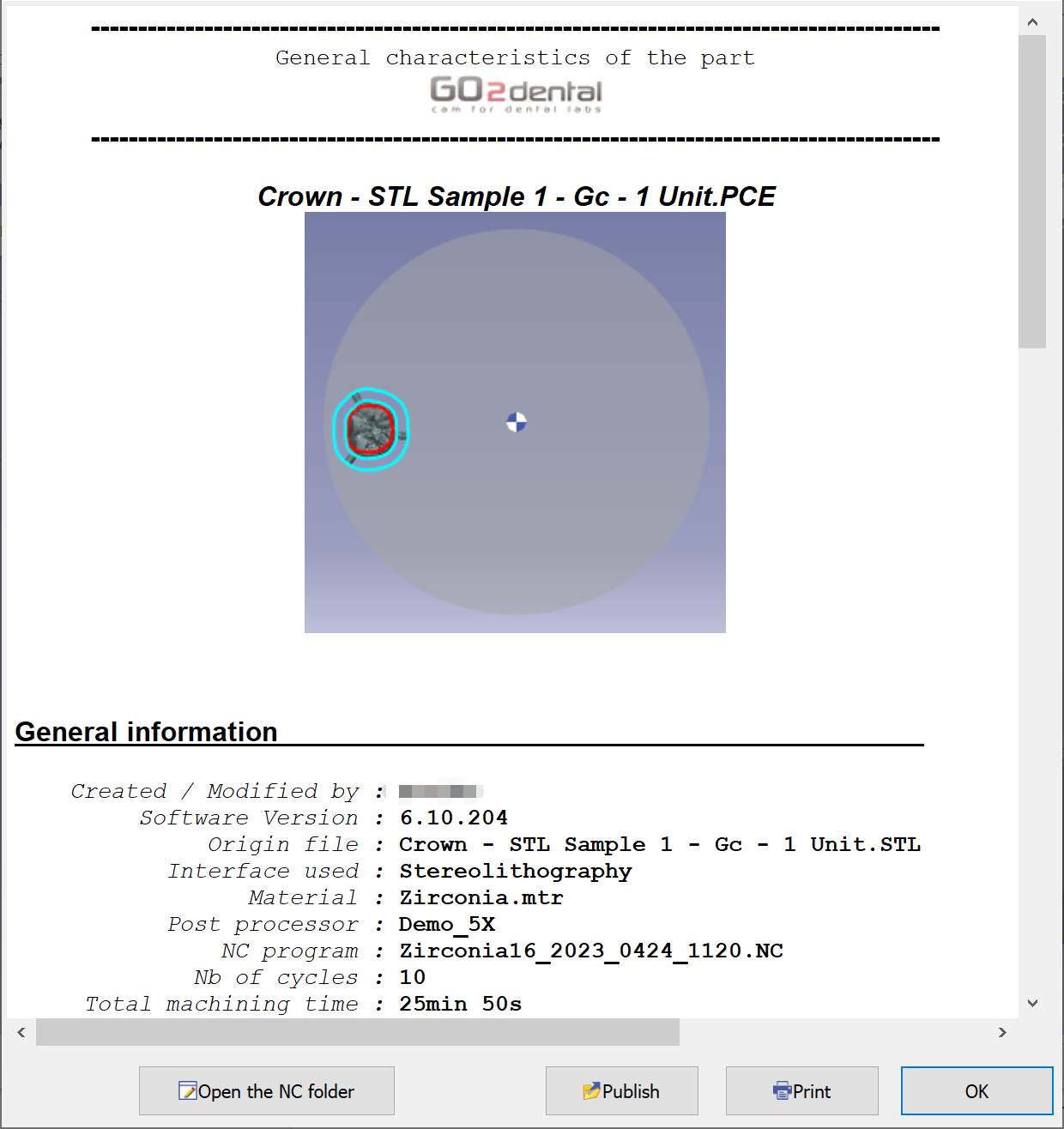
Summaries and documentations
|
This sheet shows the theoretical milling time and summarizes the tools used, selected material, and machine configuration. Click "Open the NC folder" to access the NC program in the ISO folder. |
|
▶️ Watch a video on the GUI and workflow. 
|
|
Please save the PCE file when starting a new process or exiting the software. Our engineer can use the PCE file to check the toolpath if you encounter any problems.
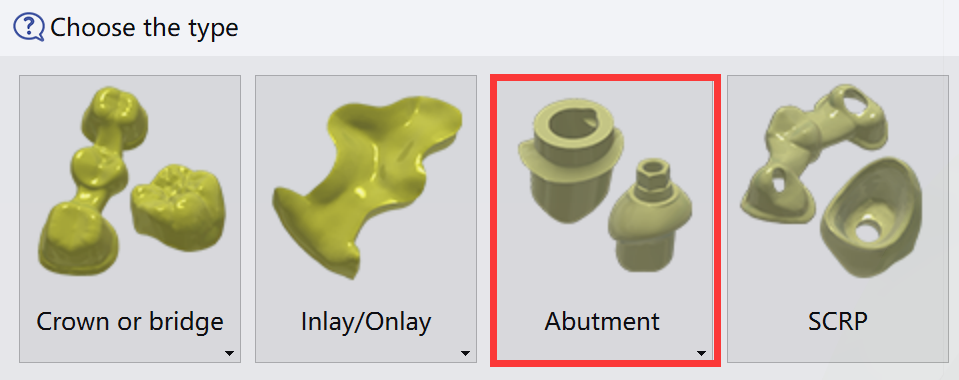
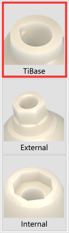
Workflow of Ti-base
Here we show only the distinct processes in the Ti-base workflow. The other processes follow the general workflow.
Import of an STL file
|
|
|
|
Validation of the import
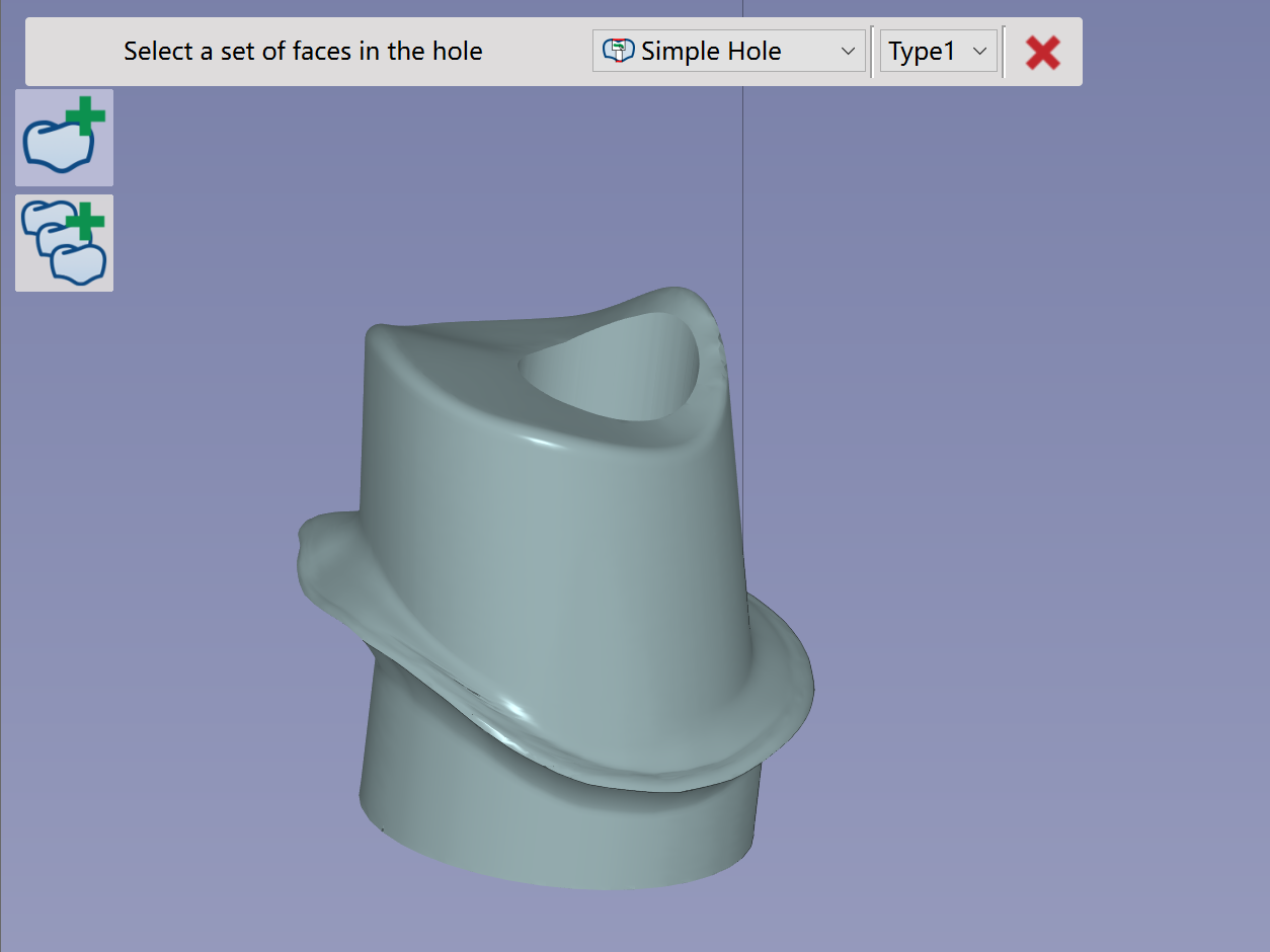
|
Rotate the Abutment to have customized shape facing upwards. |
|
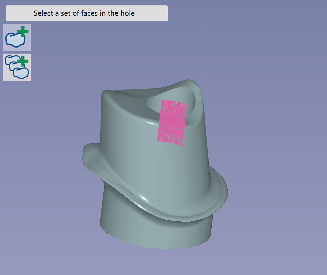
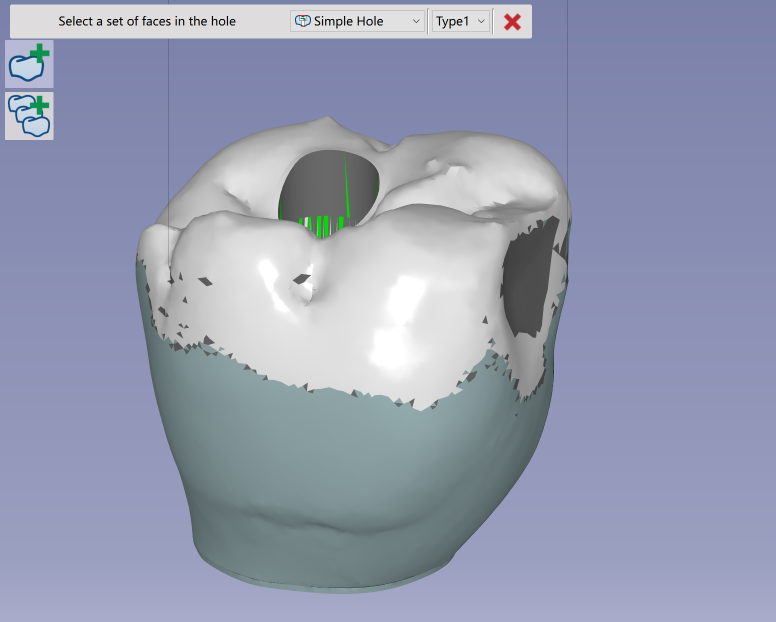
Click at the inner face of the hole, then streak along the inner face. The hole feature will be recognized then. |
|
Verify that the element has been correctly imported and validate. The next step is to Element editing in order to modify margin line, Z invert, holes or recalculate the insertion axis.
Check more details of the functions in Add File Functions | Element Editing |
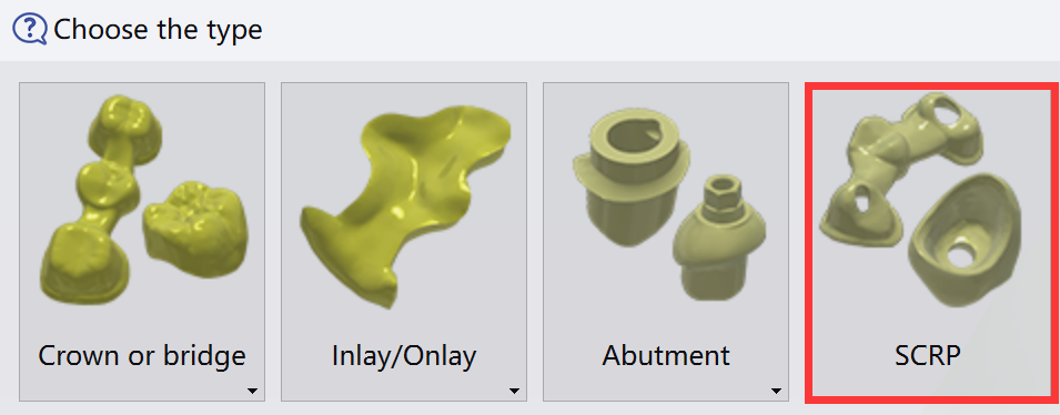
Workflow of SCRP
Hereby we only show the different processes in the workflow of SCRP. The rest processes are the same as in general workflow.
Import of an STL file
|
|
Validation of the import
|
Apply Automatic mode or Visual mode to define the insertion axis of the SCRP element. The cavity of SCRP will be machined with 5X toolpath. The 5X toolpath will use the defined insertion axis as tool axis. |
|
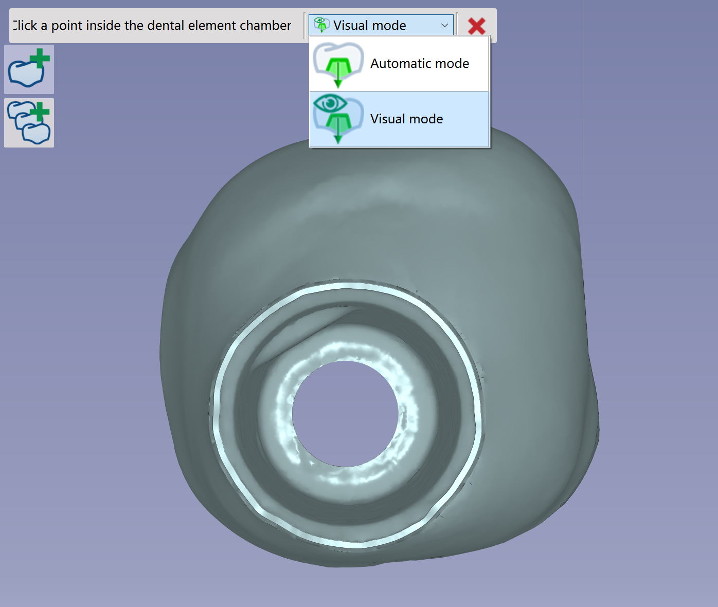
Rotate the SCRP to have occlusion side facing upwards. |
|
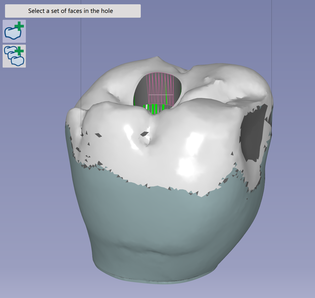
Click at the inner face of the hole, then streak along the inner face. The hole feature will be recognized then. |
|
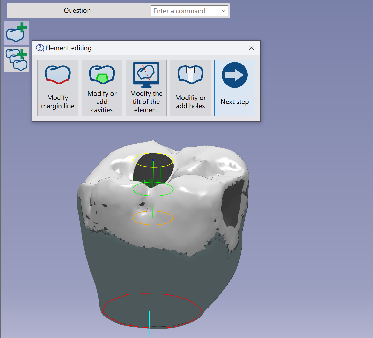
Verify that the element has been correctly imported and validate. The next step is to Element editing in order to modify margin line, Z invert, holes or recalculate the insertion axis.
Check more details of the functions in Add File Functions | Element Editing
|
|
▶️ Watch a video on workflow of SCRP. 
|
|