
General workflow
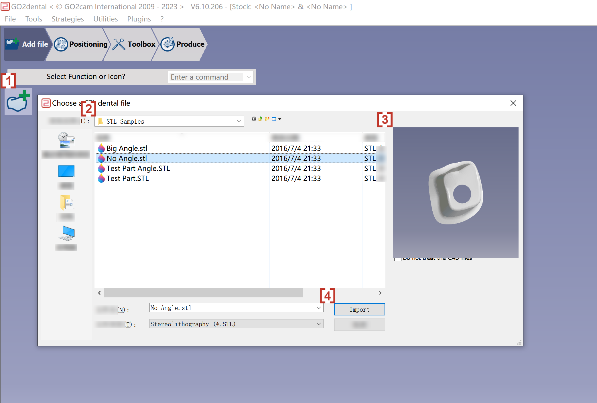
Import of an STL file
|
|
|
▶️ Watch a video on Workflow of Pre-Milled Blocks Configurations. 
|
|
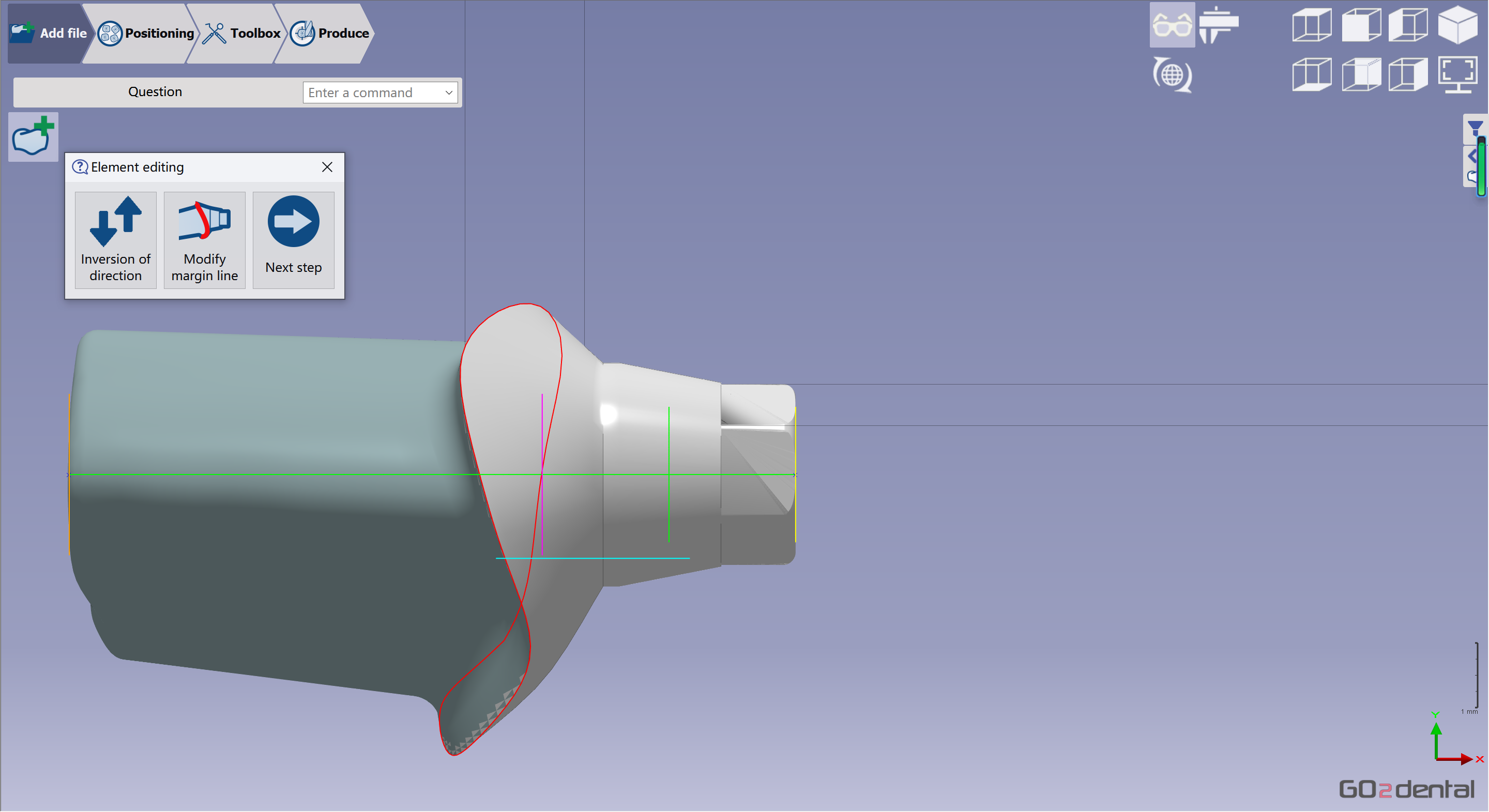
Validation of the import
|
Verify the element was imported correctly and validate it. Next, edit the element to modify the margin line or invert the direction.
|
Material selection
|
A dialog box opens to select the material.
|

|
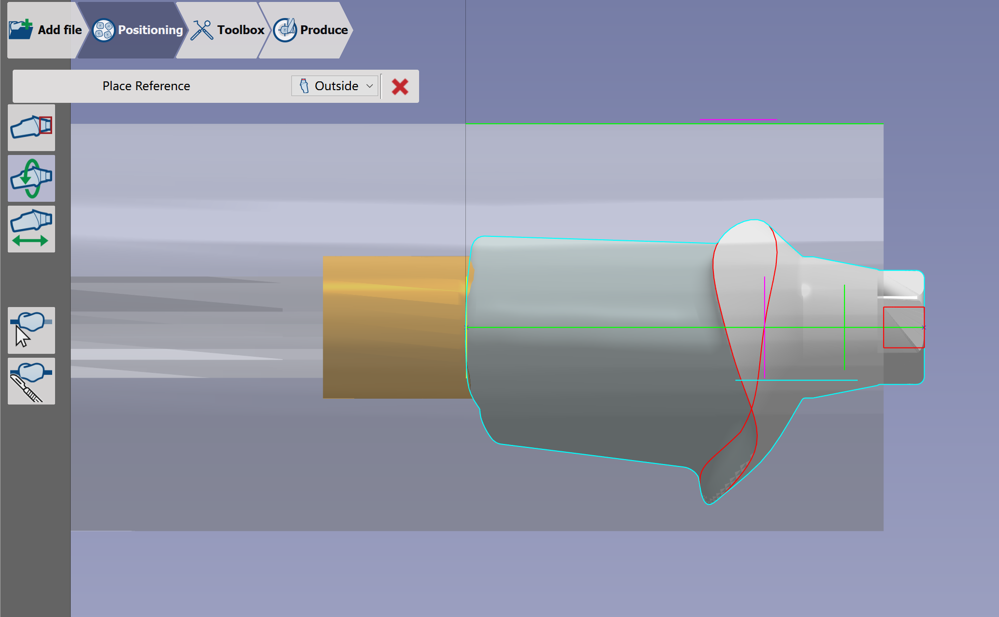
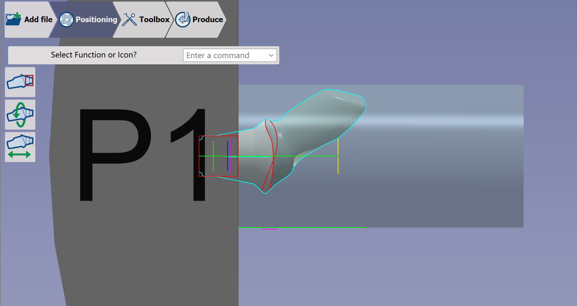
Placement of the STL file
|
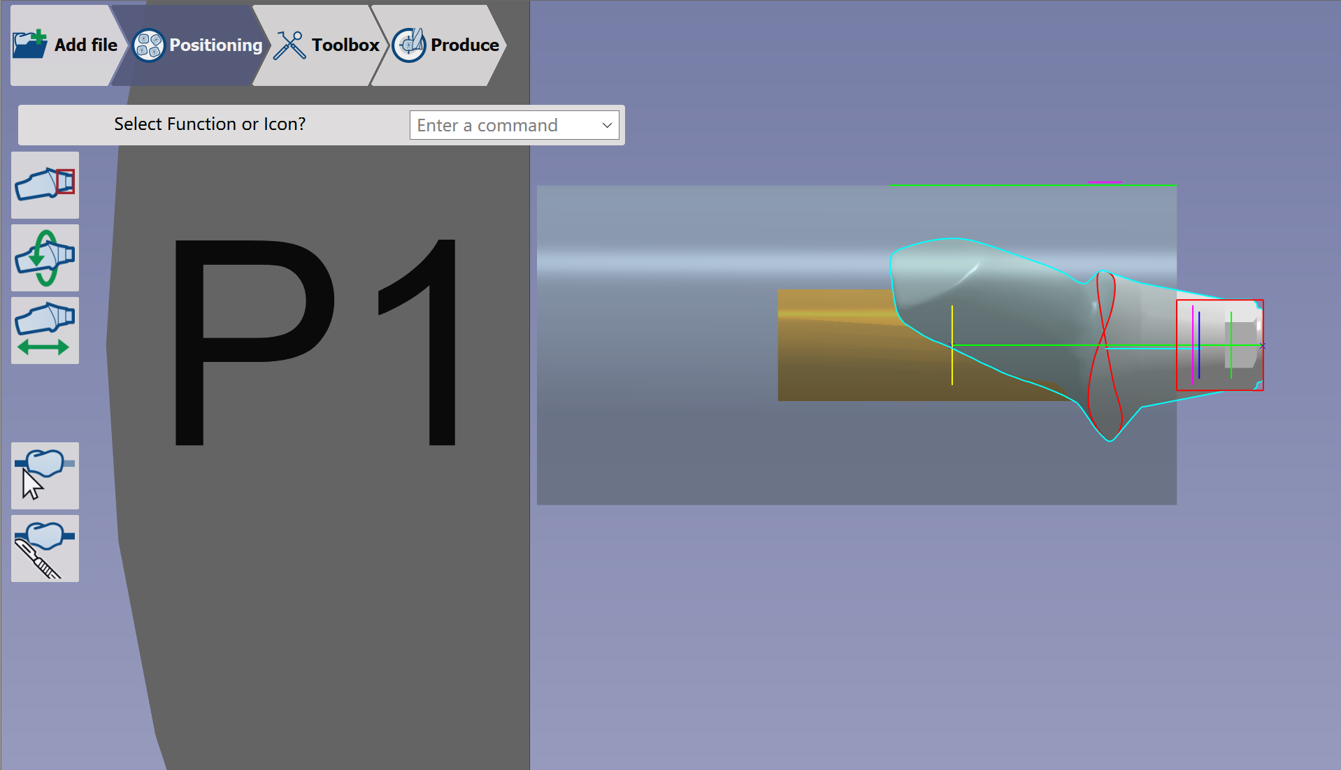
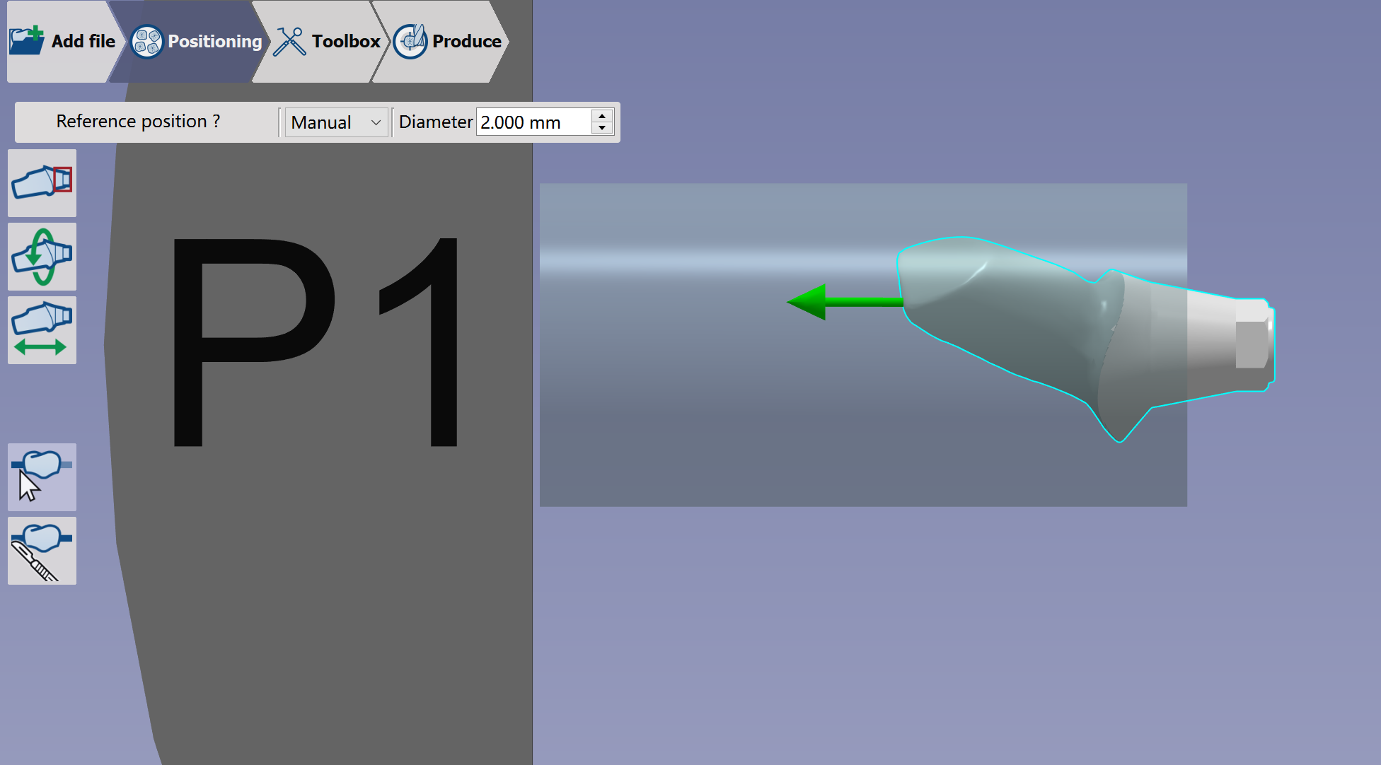
Now you enter the 'Rotation' function and must define the element's rotation angle. |
|

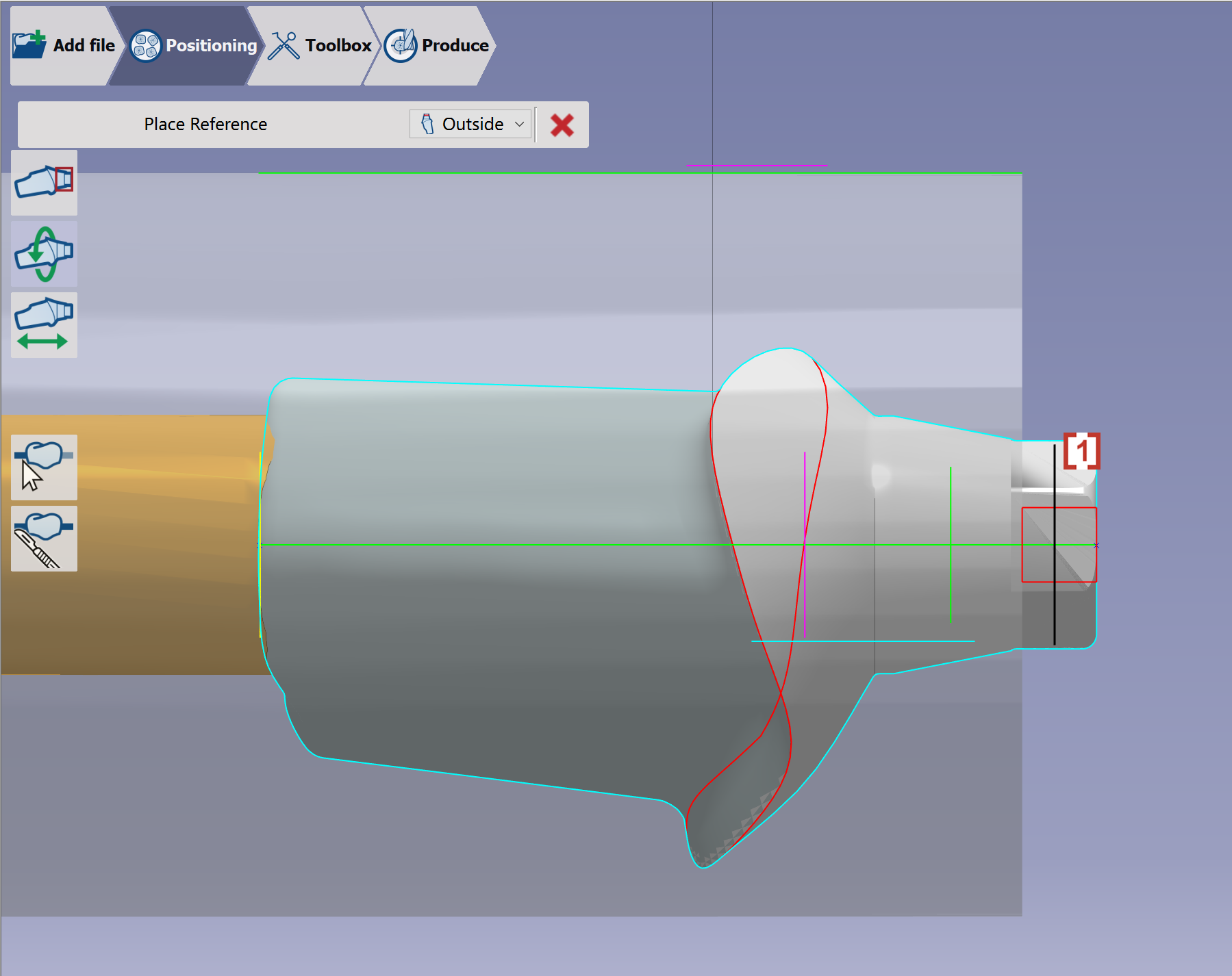
Rotation: Click an intersection curve of interface [1]. Then control its rotation to adjust the element's angle in the pre-milled blank. Click one edge of interface [2], then click the horizontal or vertical edge of rectangular frame [3]. The interface edge rotates to align with the rectangular frame edge.
|

|

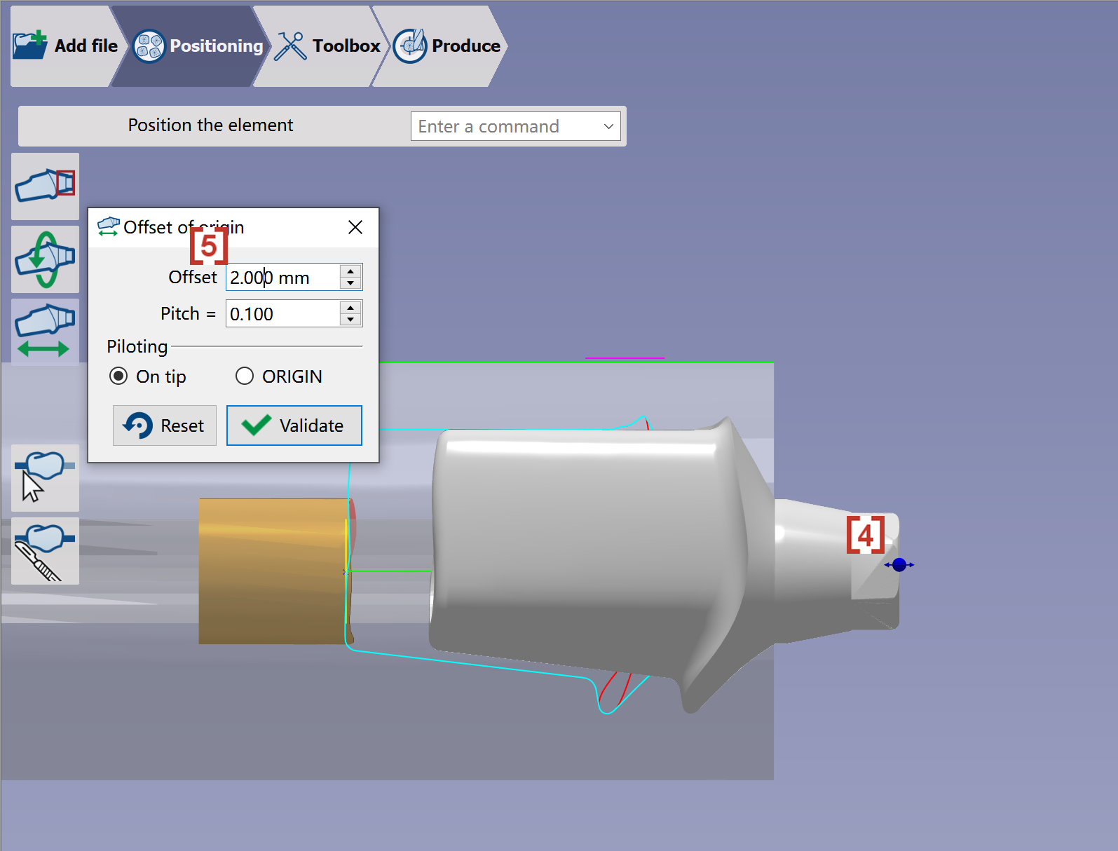
Offset of origin: Adjust the position of element in the blank along axis by dragging the blue ball [4] or giving a value of Offset [5]. |
|

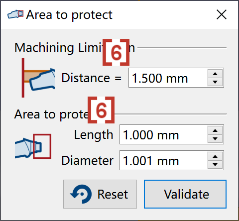
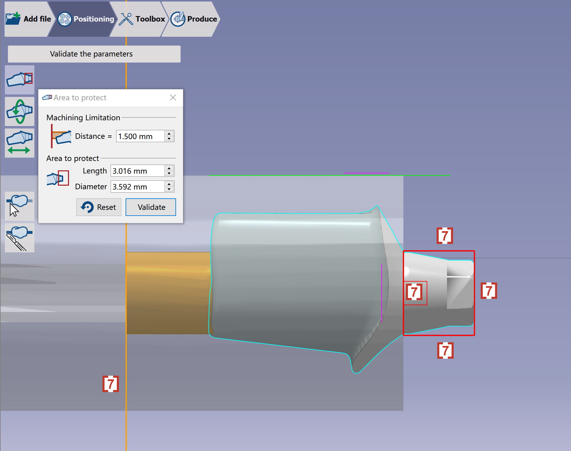
Area to protect: User can manually define the protection area of the element by giving values [6], or directly dragging the area edges in red/orange color by the mouse [7]. |
|
Creation of connectors
|
When the user validates, the software creates automatically the connectors. |
|
|
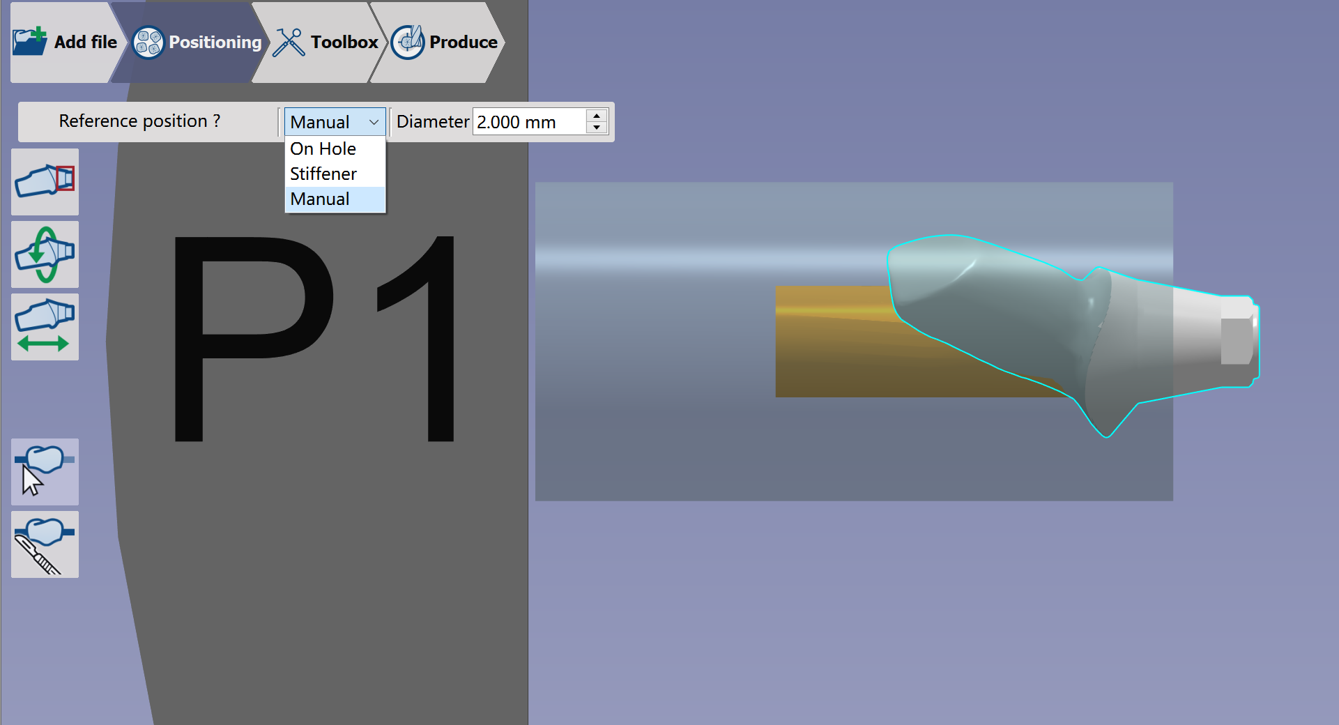
User can use Manual Connectors function to change the type and parameters of the connectors. |
|
|
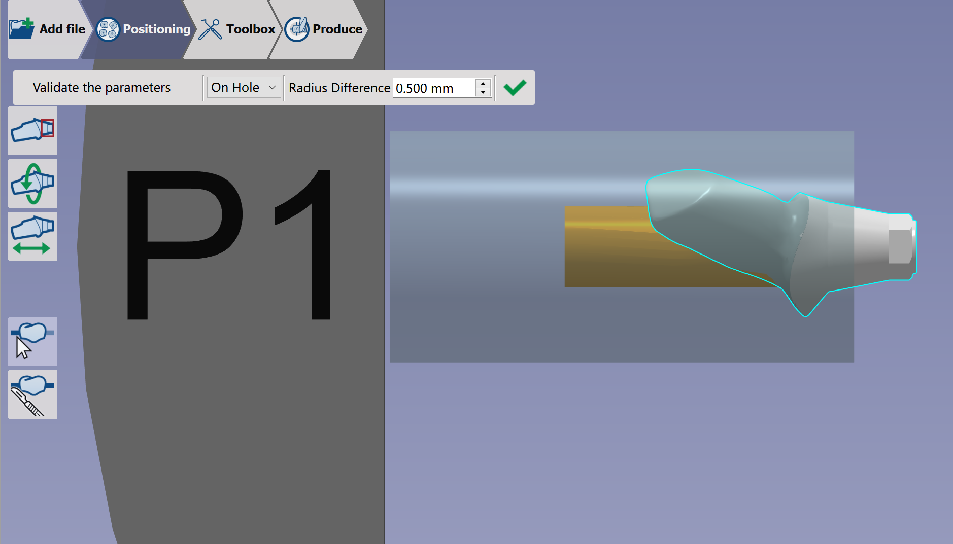
On hole: The connector is positioned automatically on the hole. This is the default type to be automatically created. Radius Difference defines the radius difference between the hole and connector.
|
|
|
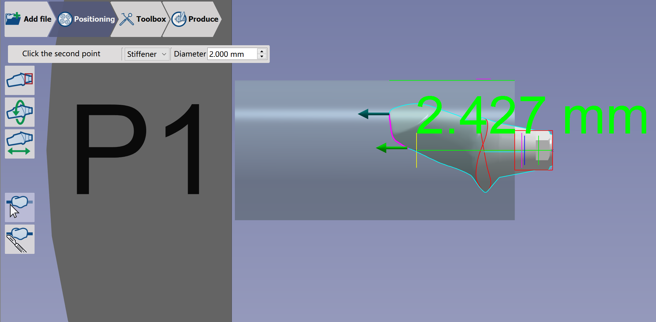
Stiffener: You have to indicate two points on the element to define the position of the connector. |
|
|
Manual: Possibility to position the connector anywhere on the 3D part |
|
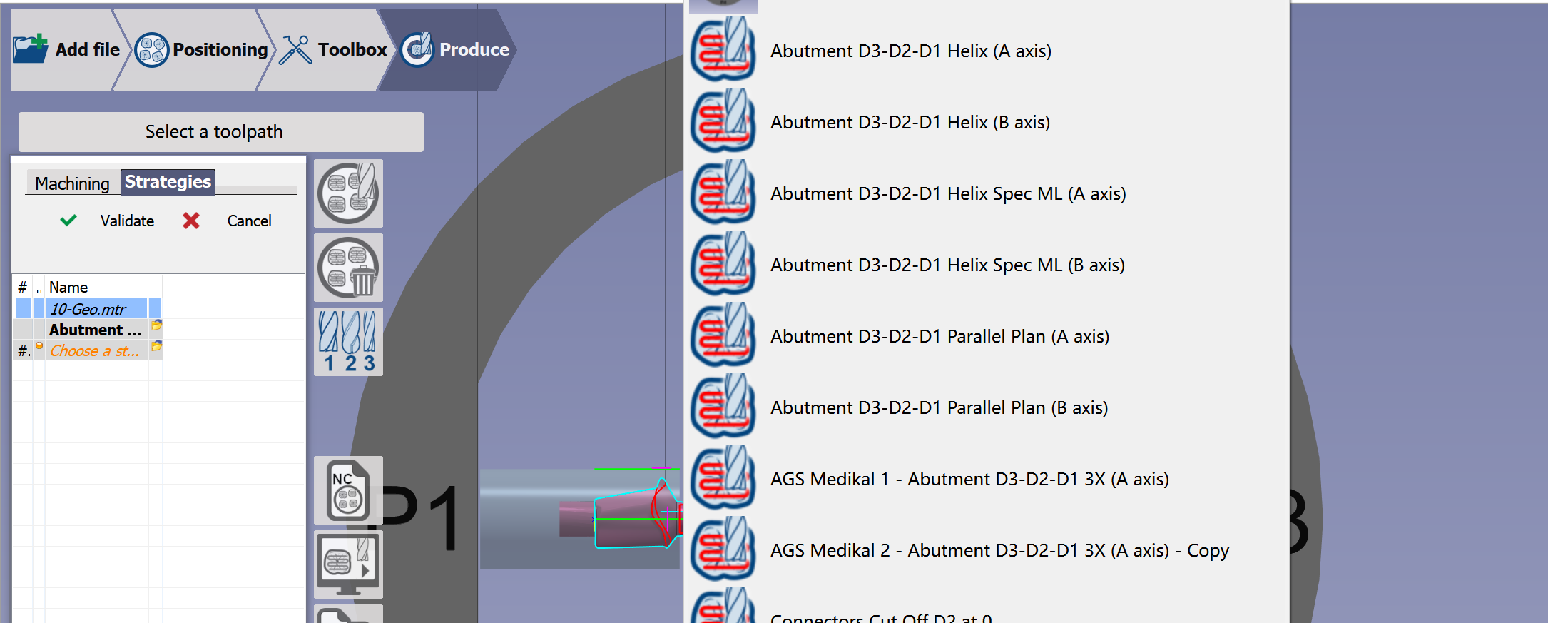
Selection of the milling strategy
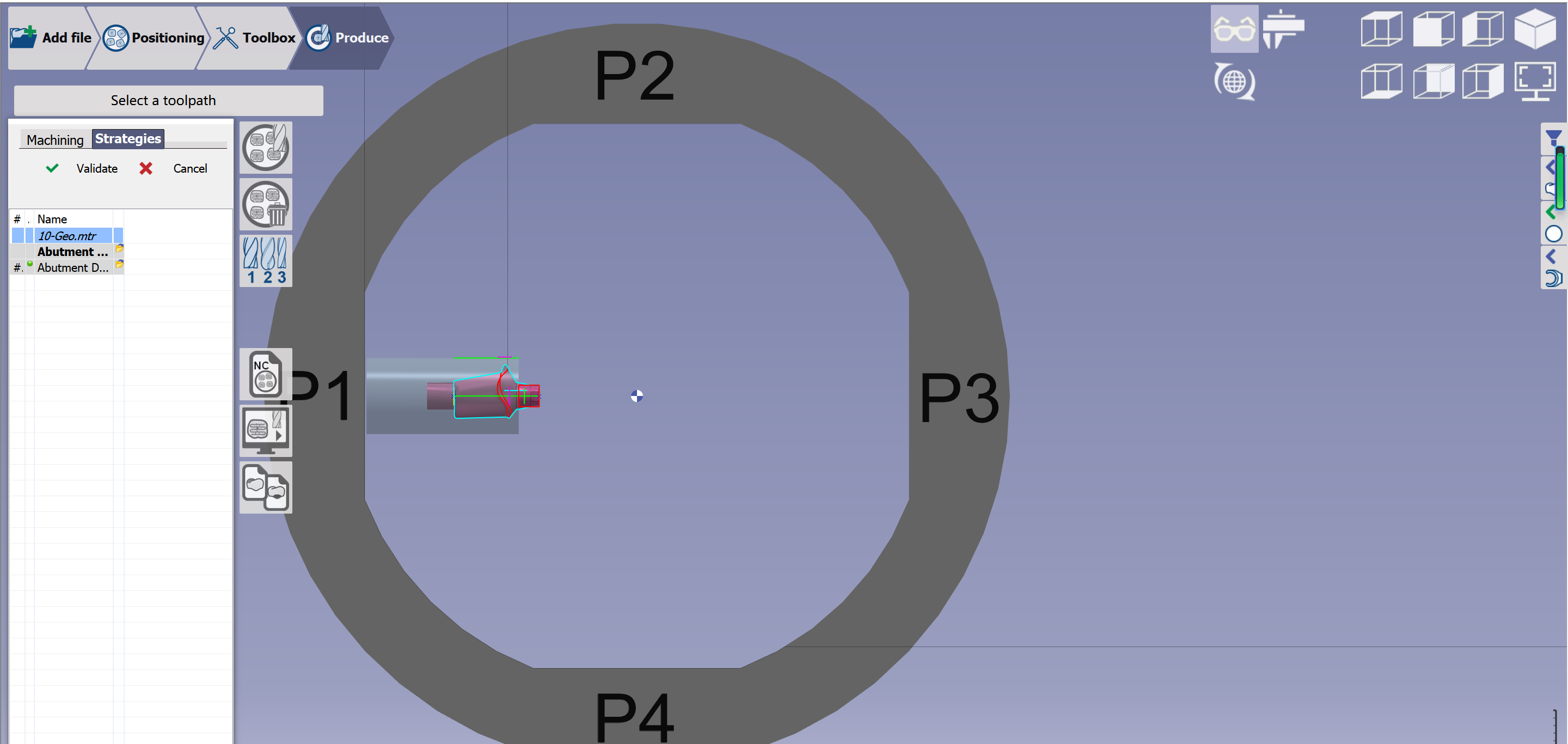
|
GO2dental will calculate the toolpaths and generate the NC program. |
|
Strategies can also be applied with a right click on the stl: |
|
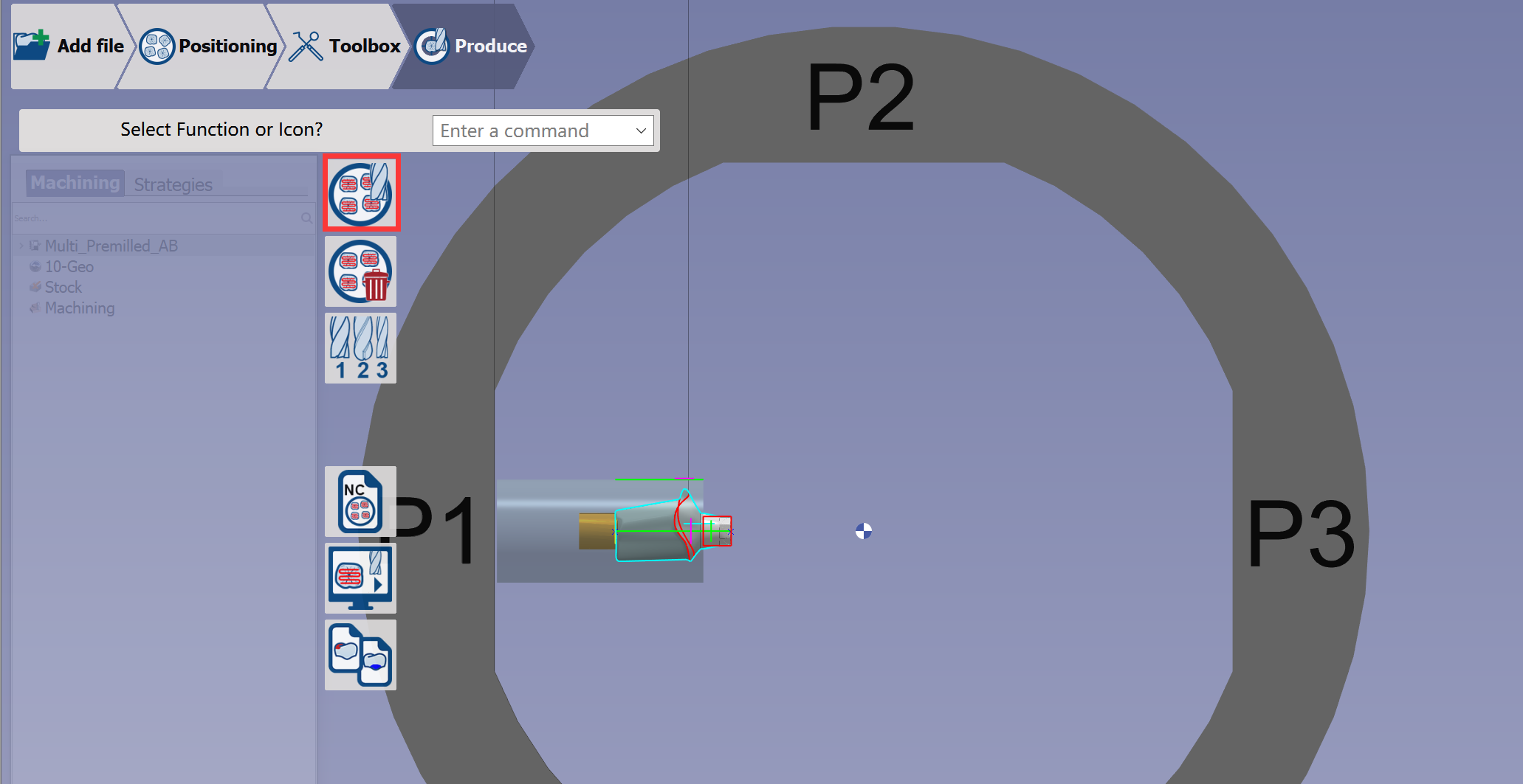
Calculation of Toolpaths
|
Click at the button 'calculation of toolpaths' and wait until the calculation ends.
|
|
Summaries and documentations
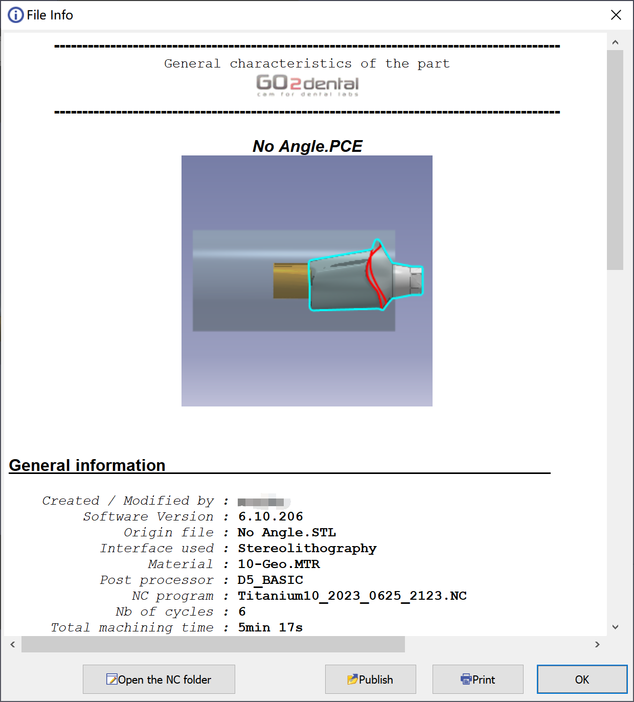
|
At the end of the calculation, this sheet informs about the theoretical milling time and recaps the tools used, the material selected as well as the machine configuration. Click on ″Open the NC folder″ to have access to the NC program in the ISO folder. |
Please save the PCE file when you start a new process or exit the software, our engineer can help to check the toolpath with the PCE file if you meet any problem.
Workflow of Analog Pre-milled Blocks
Hereby we only show the different processes in the workflow of Analog Pre-milled Blocks. The rest processes are the same as in general workflow.
Creation of connectors
|
There is no function to add connector in Analog Pre-milled Blocks configuration because the block material is inversely mounted on the fixture comparing with the general workflow. Customer needs a special OEM folder to have the Analog Pre-milled Blocks configuration. If you need this solution, please contact your reseller. |
|