
|
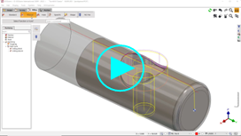
How to machine a profile that is evolutive on Z axis?
|
|
|
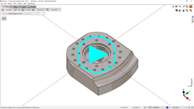
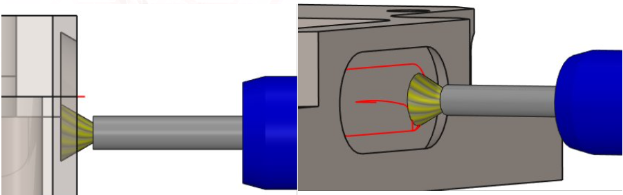
The profile chosen in the example is on a solid, so we choose the ‘edges path’ option for selection. But the process is the same for any other situation, for example a wireframe geometry with a Z evolution.
You can see that the cycle label shows: ‘Prf/D0’ which means: ‘The Z is on the profile / Depth = 0'
|
|
|
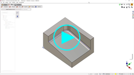
Special case: How to machine a profile that is evolutive on Z axis but on bottom of shape?
|
|
|
The selection of profile is done with the same tip as before, by clicking the Top Z button then the background! Then set the depth of the shape. Choose also the manual contouring option to adapt to the bottom of the shape.
|
|
|
How to reduce the helix angle of Interpolation but without changing the Z step?
|
|
|
You are right, in the Interpolation cycle, the helix for the plunge is defined according to the Z step. This is because the plunge angle in the tool page is set to 0. If you enter a value of plunge angle in the tool page, it will be used for the calculation of helix, without changing the Z step! |
|
|
How to program marking operations in GO2cam?
|
|
|
There are several ways to program a marking that we can separate in 2 types:
|
|
Simply write a text, and the operation will project it on the selected element and calculate the toolpath. This operation has 2 main advantages:
|
|
Here the purpose is to machine any type of geometry and project it on any shape. The toolpath is 3 axis milling. |
|
This is the same as before but the toolpath is generated in 4 axis simultaneous |

|
This method enables to wrap a text around a cylinder and then to program a marking operation and generate 4 axis toolpath by applying 2 axis operation. |
|
|
How to define radius correction and tool piloting in chamfering cycle?
|
|
|
There are some important considerations in the context of the control system and the parameters that you define in GO2cam. |
|
|
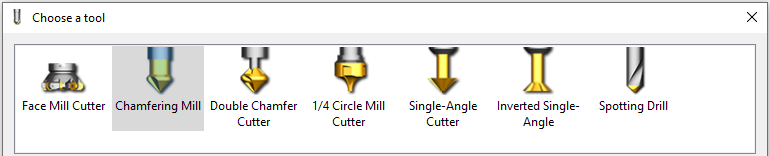
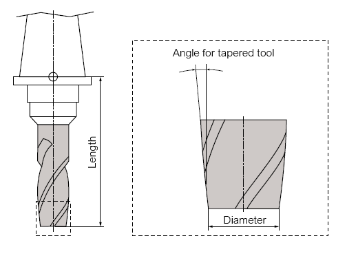
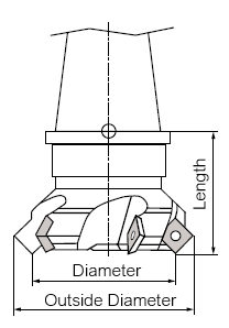
The following tool types can be used for bevel milling in GO2cam:
|
|
|
Special features when using radius correction
If the settings are incorrect, the component and/or the tool may be damaged, even if the simulation does not show any errors! It may be necessary to use a type of tool that is actually intended for other tools when applying the tool to the CNC control, as the following examples show. |
|
|
Example 1 : Siemens Sinumerik 840D |
|
|
Among the tool types, there is a truncated cone cutter (type 155), but this only offers the possibility of specifying diameters and angles. A second diameter or a cutting edge length as a parameter is not offered. |
|
|
The type of tool that fits best is the face milling cutter (type 140): here lower (small) and upper (large) diameters can be specified. The diameter relevant for radius correction with G41/G42 is the lower diameter. This is the diameter to which the tool must be measured (in the picture, the diameter). |
|
|
The tool is then displayed correctly in the simulation of the control system and can be corrected using the (lower) diameter entered in the tool table. |
|
|
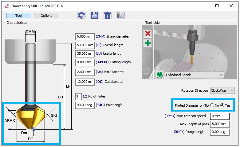
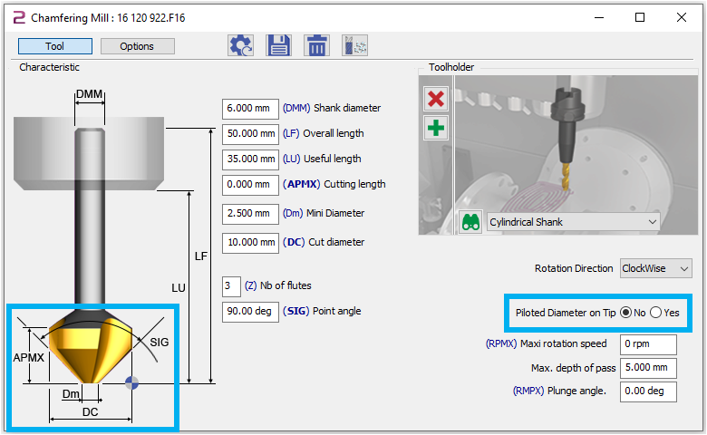
GO2cam can specify whether the diameter at the top or bottom of the cutting edge should be used for radius correction (G41/G42). In this case, the diameter Dm at the bottom (at the tip of the tool, select Yes) would have to be used. |
|
|
Example 2 : Heidenhain TNC 640 |
|
|
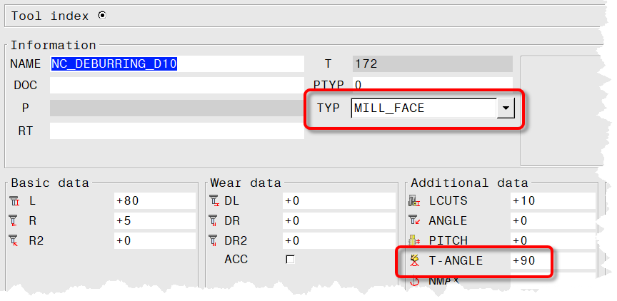
The HEIDENHAIN TNC 640 can also be equipped with the face milling cutter (MILL_FACE) tool type. In addition, the parameter T-ANGLE (angle of tool tip) must be specified (90°). However, the tool is always represented with a small diameter 0 (theoretical tip), so that it must also be measured to the theoretical tip. Therefore, the diameter relevant for radius correction with G41/G42 is the upper diameter. |
|
|
In the simulation, the tool is displayed correctly, but always with a theoretical tip (lower diameter 0). The (upper) diameter entered in the tool table can be used for correction. |
|
|
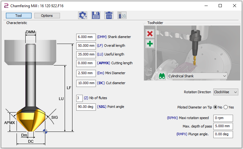
In GO2cam, the upper diameter DC must be set accordingly (select No) and the lower diameter must be specified as 0. |
|
|
The two examples above illustrate that it may be easier not to use radius correction, especially if the same tools are used on different machines or CNC controls:
|
|
|
In GO2cam, this can be achieved with the Single-Angle Cutter type. In contrast to the chamfering mill, the pilot point (control point) of the tool also changes its position to Z when the position of the pilot diameter is switched. |
|
|
How to define the profile/chamfer and Width in the chamfering cycle?
|
|
|
Also, the chamfering cycle can process chamfers that are already present in the 3D model as well as add chamfers on sharp edges. |
|
|
In the latter case, the desired bevel width must be specified manually. 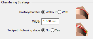
In the case of a chamfer that has already been modeled, the following edge is selected as the geometry.
For more information on the Profile / Chamfer and Width. |
|
|
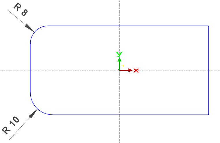
I got an error message “Tool radius too large” from my machine when machining the inner corner of my workpiece.
|
||
|
Problems always arise when the tool radius is greater than or equal to the programmed corner radius when finishing with radius correction. |
||
|
If the displayed contour is processed with a milling cutter D16mm (Radius = 8mm), there may be problems in the sharp corners on the right (corner radius = 0mm), as well as in the corner radius of 8mm. |
|
|
|
GO2cam basically offers two options for NC output in order to avoid problems with the machine later on. The parameter to control the behavior of GO2cam in these situations is located on the Strategy tab and is called Corner type. |
In Pocket+Contour Cycle: 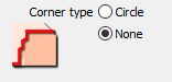
|
In Contouring Cycle: 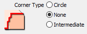
|
|
The exact settings will be discussed in the following steps: |
||
|
Corner Type(None) for Contouring cycle Sharp corners (corner radius = 0mm) or corners whose radius corresponds to the tool radius are output as sharp corners (G1-G1). Inner radii that are larger than the tool radius are output as G2/G3 as normal. |
The tool path in the contouring cycle. 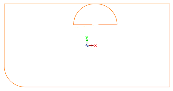
|
|
|
Corner Type(None) for Pocket+Contour cycle Here, sharp corners are displayed as such, but rounded corners are always displayed as G2/G3, but with a larger radius, which results from the tool radius multiplied by the parameter R max coef (corner R8 upper left): In the example, the factor is exaggerated as 1.2 to make the effect visible, so that a radius of 8mm x 1.2 = 9.6mm |
The tool path in the Pocket+Contour cycle. 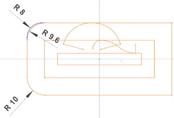
|
|
|
These options are therefore not suitable for finishing a contour where the dimensional accuracy of the inner radii is important and the tool radius already corresponds to the corner radius:
In both cases, there is no guarantee that the drawing dimension will actually be manufactured. |
||
|
Corner Type(With) for Pocket + Contour and Contouring cycle The radius again corresponds to the tool radius times the parameter R max coef, in the example again exaggerated with 1.2. This setting guarantees that there are no errors on the controller. In addition, sharp corners in the center path of the tool are avoided. However, the inner radii are again made larger than the drawing dimension. In order to finish a contour with radius correction, where the dimensional accuracy of the inner radii is important, a tool must be used whose radius is smaller than the smallest inner radius. |
The toolpath of Contouring cycle is shown below. (The pocket+contour behaves in the same way). 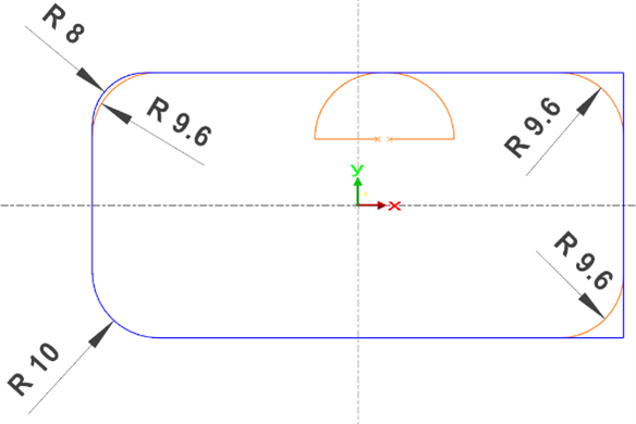
|
|
|
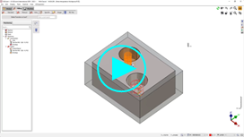
How to define a starting point for pocket machining?
|
|
|
When you define a pocket in GO2cam, you cannot select the entry point of the tool, this is automatically done by the software. For a user to force the entry point for the pocket, the Prepierced hole command is necessary. The concept is to define and drill a hole in the pocket in the area preferred. This allows the tool to start cutting through the stock from its sides which is the cutting part for flat-end mills. The command will allow the tool the start the pocket machining from this hole. There are 2 ways to define the pre-drilled hole:
|
|
|
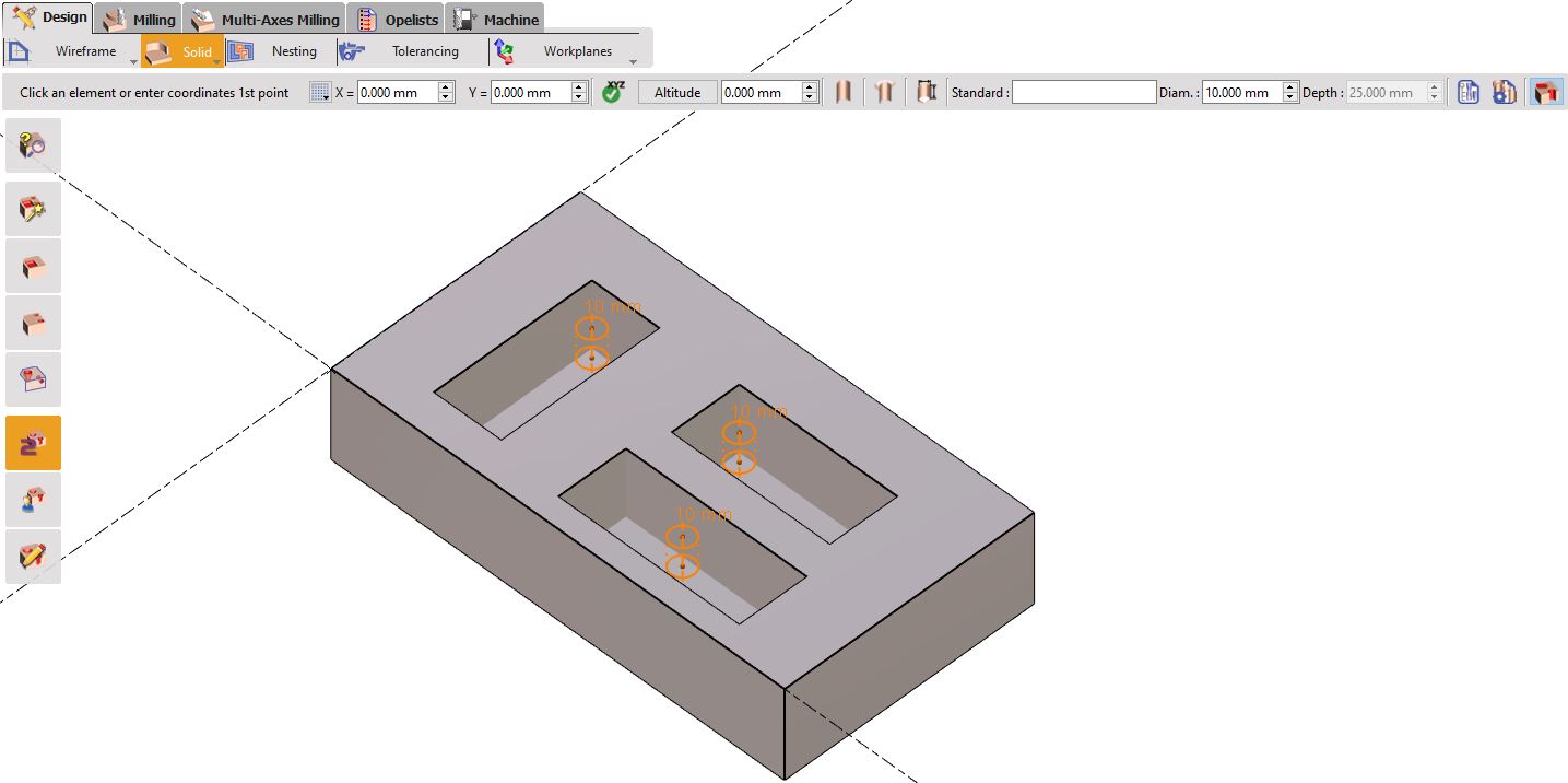
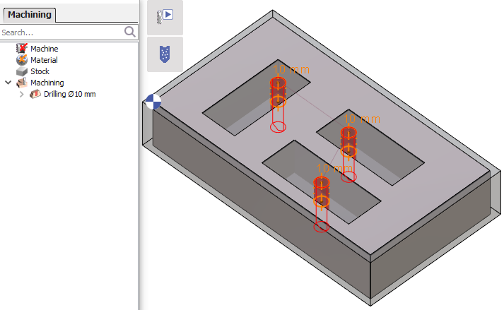
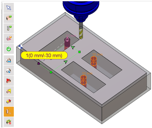
1/ Manual creation of a prepierced hole. The first step requires to define a standard hole or simply design a circle on the preferred location in the Design tab.
Followed by the drilling of the whole, either automatically or manually.
Finally, during the geometry selection step you can choose the command Prepierced hole and select the hole geometry. The starting point of the cycle is then defined on that hole.
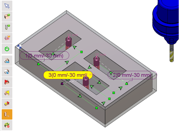
For instance, in the example on the right, for multiple pockets selected, you can define the starting points for each of them by multiple selection of the holes. Note: After clicking in the command, you have to press and hold the Ctrl key to select multiple holes.
|
|
|
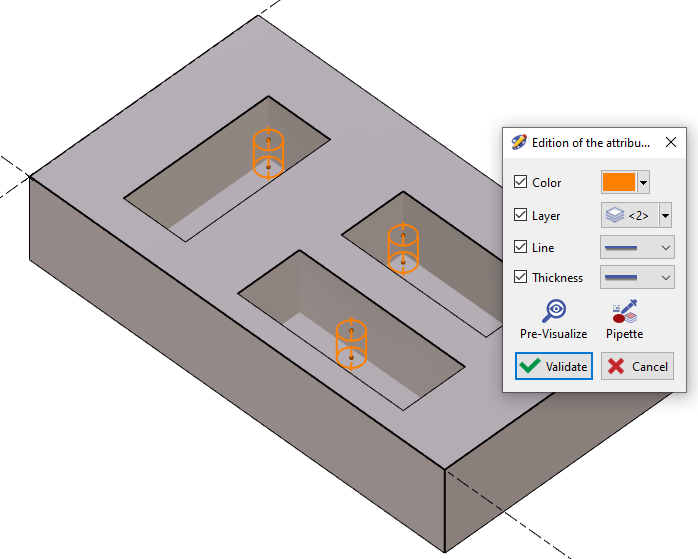
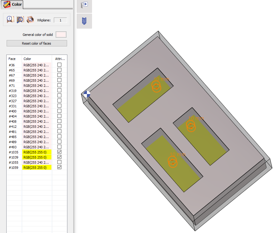
2/ Automatically with the use of an opelist The first step in defining the automatic prepierced hole is to create the holes geometry in a separate layer. In this case the holes are set to layer 2.
Also change the color of the bottom faces of the pockets to a different color, for instance we change it to yellow here.
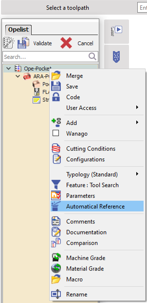
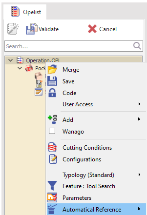
At this point, you can now create or modify an existing opelist and apply an automatical reference to it by right clicking on the opelist.
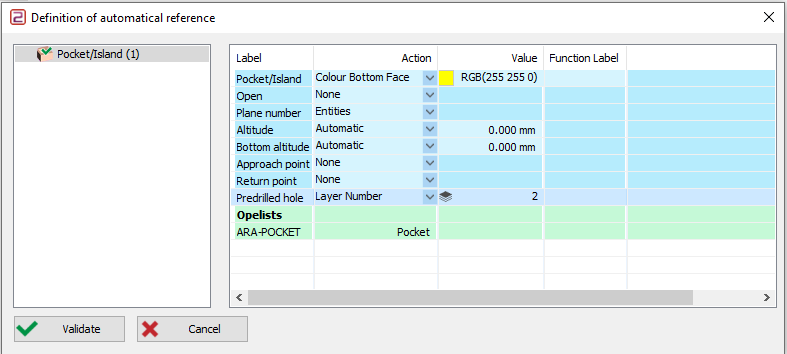
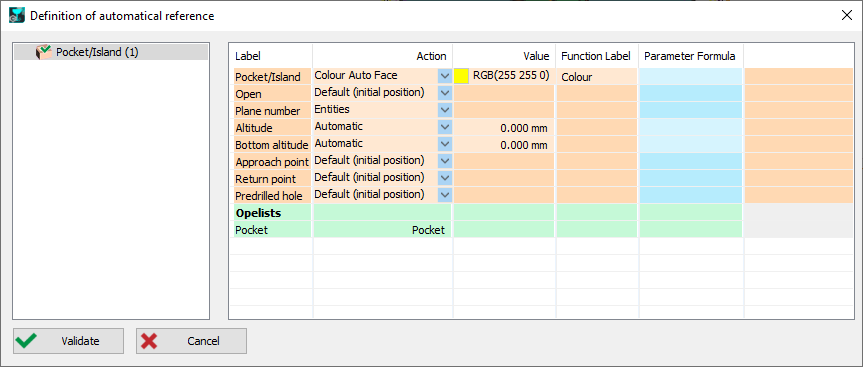
For the pocket/island cycle, go to the Predrilled hole Label and change the Action to Layer Number and the Value to the layer defined for holes which is 2 in this case. and for the Pocket/island Label, change the Action to Colour Bottom Face and the Value to the same yellow color chosen. Validate the automatical reference and validate the opelist.
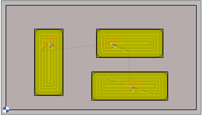
Now if you apply the opelist on the workpiece, the prepierced hole command is automatically considered and the starting point for each pocket is at the defined hole. |
|
|
How to carry out deburring on a workpiece in GO2cam?
|
|
|
3 methods are possible depending on the package available: |
|
|
1/ Automatic deburring with chamfering This method is available for 2X & 2.5X machining cycles. In this case, no dedicated deburring cycle is available. Deburring is carried out through the Chamfering cycle. See the video on the right for an example. |
|
|
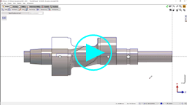
2/ 3X Deburring Access to the 3X Deburring cycle is available if 3X milling option is activated. The cycle can be found in the Milling tab, under the Shape menu. Simply Select the whole solid, choose the tool and apply the cycle. The deburring will be calculated. Watch the video on the right for an example. |
|
|
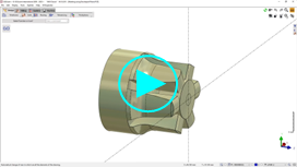
3/ 5X Deburring 5X Deburring is available if the 4-5X machining option is activated. The cycle can be found in the Shape Milling tab, under the 5X Expert menu. The process is similar to 3X deburring. The video on the right shows an actual deburring cycle on a part. |
|
|
Why is my stock no longer calculated on previous cycles when I re-execute an operation?
|
|
|
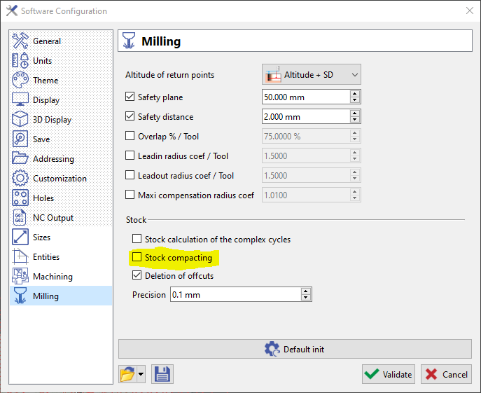
Perform an update on the overall machining operation is a quick fix for this issue. Alternatively, we may deactivate the Stock Compacting setting by selecting Tools>Options>Milling and then unchecking the Stock compacting option. |
|
|
|
|
How to automatize the machining of pockets by the colour of their solid faces?
|
|
|
This is done by defining an automatical reference for the opelist: |
|
|
During the creation or edition of an opelist, for the pocket cycle, access the Definition of automatical reference window. |
|
|
For the pocket cycle in which to define the automatical reference, set the: Action > Colour Auto Face Value > leave it to the default chosen Function label > type Colour as the label Validate and save the opelist. |
|
|
On the application of the opelist, you will be able to select the required colour using the pipette or by entering the RGB value in the opelist adjustment window. Select the tool and make adjustments to the cycle if required and simply validate the opelist. The geometry selection will be and pocket machining will be done automatically based on the colour defined. |

|
|
Can I machine sloped ribs with 2 axis milling in GO2cam?
|
|
|
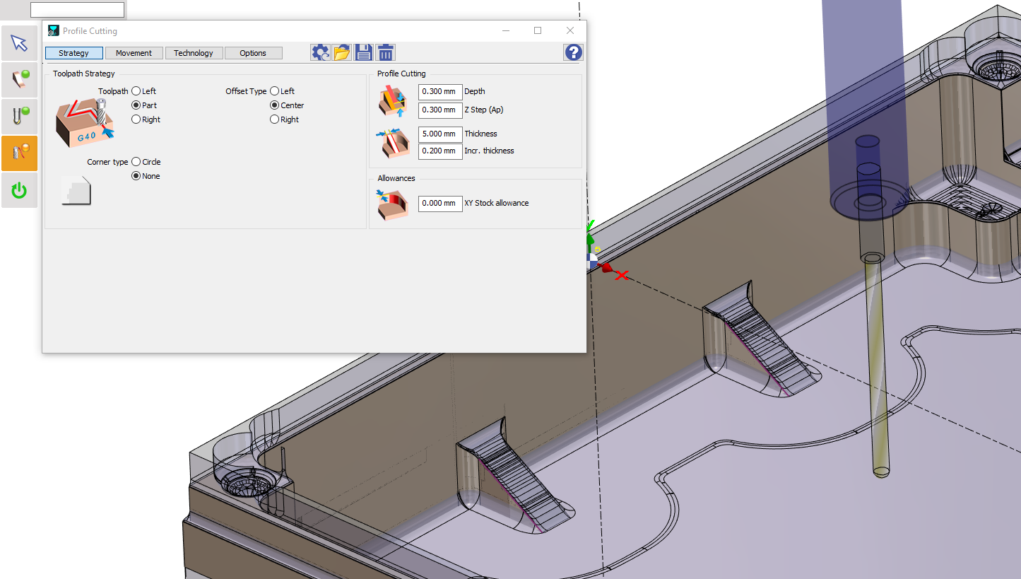
GO2cam offers a specific cycle; Profile Cutting cycle which applies a 2.5 axis machining operation on a wireframe to carry out the machining operation. The process is as shown below: |
|
|
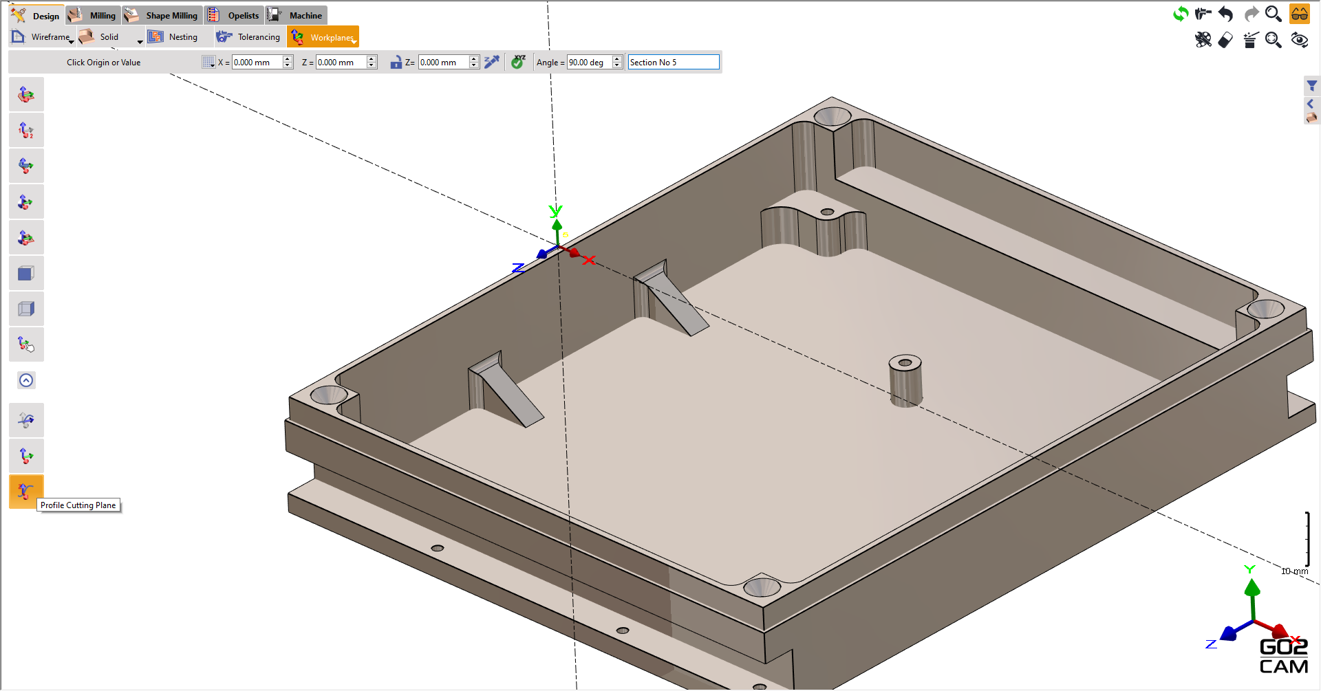
The first process involves creating a specific workplane called the Profile Cutting plane. This is located in the workplanes creation tab on expanding the toolbar. The last command is the required one. The X-Y plane governs the machining direction and since we want to machine in its longitudinal direction, set the angle to 90deg. Click on any point to define the origin, in this case, the same origin. |
|
|
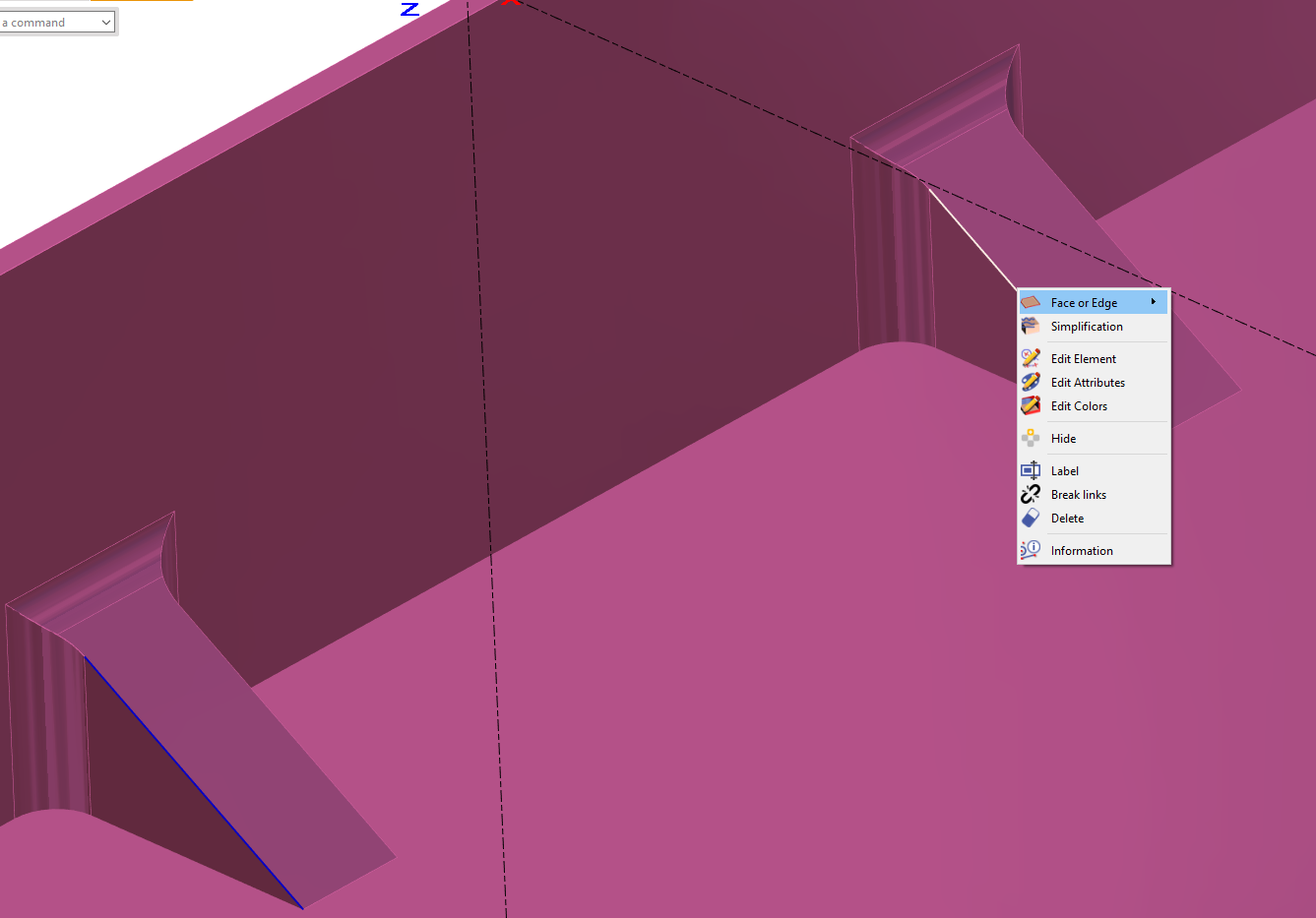
Define the wireframe either by drawing it or extracting it from the solid. This is essential to provide a reference for the geometry selection.
|
|
|
Finally define the Profile Cutting cycle located under Specific tab. Choose the extracted edges as profile, define the tool and the profile cutting strategies and calculate. 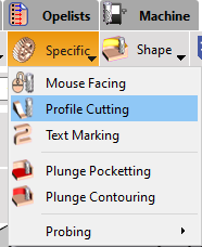
|
|
|
The slope machining is as such. 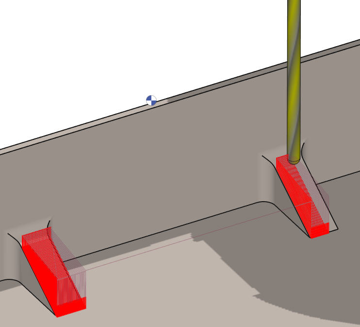
|
Watch a video below showing the process.

|
|
How machined tapered sides of a pocket in one go? |
|
GO2cam now offers the ability to use ‘Inverted Single-Angle’ cutter with Pocket operation. As you select the tool, and proceed to the parameters of the Pocket, notice that some parameters of the pocket cycles are greyed out. |
|
|
What is the purpose of the Leadin Depth and Leadin Feedrate options? |
|
These options are designed to provide more control over drilling cycles, particularly for inclined holes. The Leadin Depth specifies the initial depth at which a reduced feedrate (Leadin Feedrate) will be used. This allows for a smoother start and reduces the risk of tool breakage or excessive wear, especially when the drill is not fully engaged. Once the drill reaches the Leadin Depth, the feedrate will automatically increase to the defined value. |